IBASE MI912 User Manual
Page 30
INSTALLATIONS
26
MI912 User’s Manual
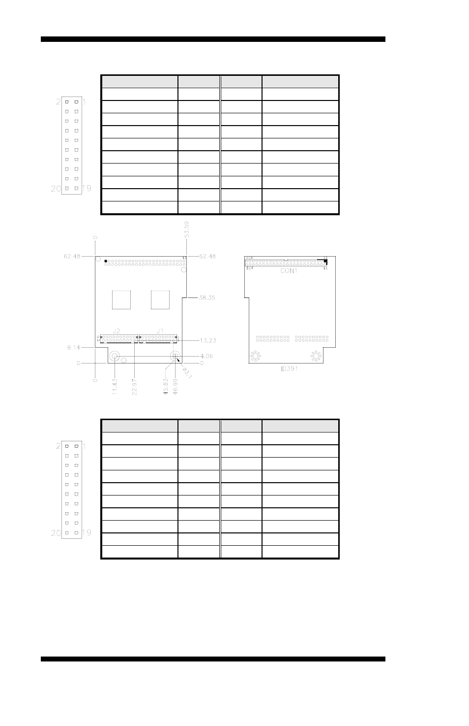
ID391 – J2 DVI Connector
Signal Name
Pin #
Pin #
Signal Name
TDC1-
2
1
TDC1+
Ground
4
3
Ground
TLC-
6
5
TLC+
+5V
8
7
Ground
NC
10
9
HPDET
TDC2-
12
11
TDC2+
Ground
14
13
Ground
TDC0-
16
15
TDC0+
NC
18
17
NC
DDC_SC
20
19
DDC_SD
ID391D – J1, J2 1
st
/2
nd
DVI Connectors
Signal Name
Pin #
Pin #
Signal Name
TDC1-
2
1
TDC1+
Ground
4
3
Ground
TLC-
6
5
TLC+
+5V
8
7
Ground
NC
10
9
HPDET
TDC2-
12
11
TDC2+
Ground
14
13
Ground
TDC0-
16
15
TDC0+
NC
18
17
NC
DDC_SC
20
19
DDC_SD
Remarks: When using dual DVI, the first DVI video output is through J1. After
setting the drivers in Windows, then the second DVI output (via J2) will function.
ID391D and ID391 are different since the latter (ID391) has video output via J2.
The pin assignments of J1 and J2 are the same.