Chapter 9, Installing mini pci-e module, Chapter 10 – IBASE FWA6304-D25 User Manual
Page 17: Lock power connector, Chapter 9 installing mini pci-e module, Chapter 10 lock power connector
Advertising
FWA6304-D25 Series
User’s Manual
16
Chapter 9
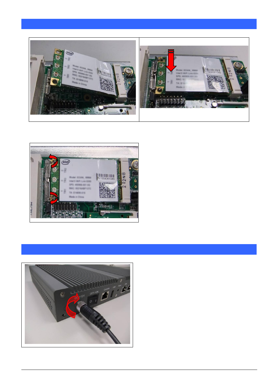
Installing Mini PCI-e Module
Fig. 9-1 Insert Mini PCI-e module
(Supports USB signal only)
Fig. 9-3 Release two clips to remove module
Fig. 9-2 Push down the module into socket
Chapter 10 Lock Power Connector
Fig. 10-1 Plug power connector into power jack
Advertising