The connectors – IBASE FWA6304-D25 User Manual
Page 9
FWA6304-D25 Series
User’s Manual
8
The Connectors
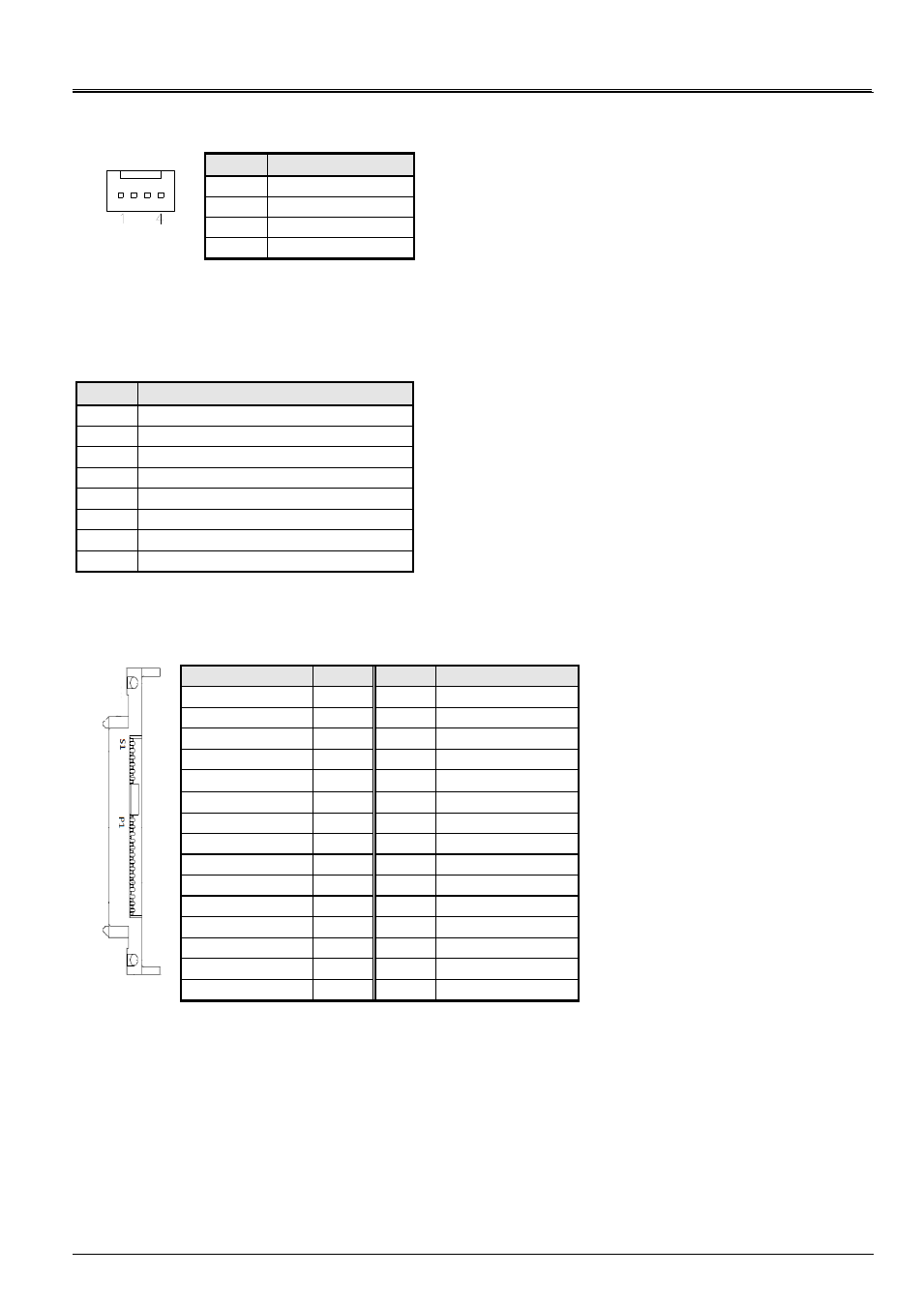
FAN1: System Fan Power Connector
FAN1 is 4-pin header for System fan power. The fan must be a 12V fan.
Pin #
Signal Name
1
Ground
2
+12V
3
Rotation detection
4
Control
CN1, CN2, CN3, CN4: 10 / 100 / 1000 LAN Ports
CN5: USB Connector
CN6: COM1 RJ45 Connector
Pin #
Signal Name (RS-232)
1
RTS, Request to send
2
DTR, Data terminal ready
3
TXD, Transmit data
4
Ground
5
Ground
6
RXD, Receive data
7
DSR, Data set ready
8
CTS, Clear to send
CN7: SATA SSD Dock
The SATA SSD dock combines a SATA power connector and a SATA interface connector.
Signal Name
Pin #
Pin #
Signal Name
GND
S1
P1
+3.3V
A+
S2
P2
+3.3V
A-
S3
P3
+3.3V
GND
S4
P4
GND
B+
S5
P5
GND
B-
S6
P6
GND
GND
S7
P7
+5V
P8
+5V
P9
+5V
P10
GND
P11
GND
P12
GND
P13
+12V
P14
+12V
P15
+12V
J1: SO-DIMM DDR3 Socket
J2: Mini PCI-e Connector (USB signal only)
J3: SPI Debug Port (Factory use only)