2 receiver, Receiver – IDK OPF-H1000-A User Manual
Page 12
OPF-TH1000-A/OPF-RH1000-A User’s Guide
12
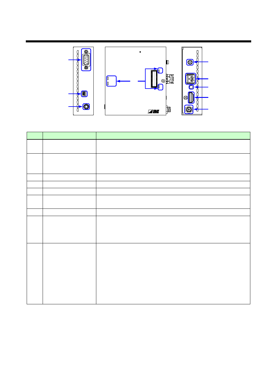
4.2 Receiver
POWER
SIGNAL
POWER
SIGNAL
RX
O PTICAL Rx for HDMI
O PF-RH1000-A
D
C
5
V 2
A
F
G
O
P
T
IC
AL
O
U
TP
U
T
H
DM
I
TX
R
S-2
3
2
C
Rx
O
U
TP
U
T
AU
D
IO
D
IP
-SW
CLASS 1 LASER PRODUCT
クラス 1 レーザ製品
①
②
③
④
⑤
⑥
⑦
⑧
⑨
Panel drawing (OPF-RH1000)
#
Part name
Description
①
HDMI output connector Output connector for HDMI signals
Sink devices such as TVs can be connected.
②
I/O connector for
extension
Digital optical signal I/O connector for extension
Factory installed SFP module allows fiber optical cables to connect
OPF-TH1000 (transmitter) and OPF-RH1000 (receiver).
③
AC adapter connector
Connector for the attached AC adapter
④
Cable fixing hole
Hole for the supplied cord clamp
⑤
RS-232C connector
Connector for D-sub 9 pin
⑥
Audio output
connectors
Output connector for audio signals.
(Those audio signals were not de-embedded.)
⑦
Frame ground
Ground for indoor ground terminal
⑧
LED lights
POWER: Lights when power is supplied from the AC adapter.
SIGNAL: Lights when video signal is valid.
TX: Lights when valid codes are sent
RX: Lights when the receiver fiber receives valid codes.
⑨
DIP Switches
DIPSW1:
Sets the transmission reaction time of Hot Plug Detect (HDMI Pin 19).
• “OFF”: Hot Plug Detect signals of the sink device is transmitted to the
source device if they are 0.1 second or longer.
• “ON”: Hot Plug Detect signals of the sink device is transmitted to the
source device if they are 1 second or longer (not transmitted if 0.9
seconds or less).
DIP SW2 to 4:
Nothing is assigned. Please do not touch these switches.