G” series - installation and connection, Plumbing, Electrical – Insinger I Series Food Waste Disposer User Manual
Page 8: Testing
Page 8
Insinger Machine Company 2005
“G” SERIES - Installation and Connection
NOTE: PLUMBING AND ELECTRICAL CONNECTIONS SHALL BE MADE IN COMPLIANCE WITH APPLICABLE
LOCAL CONSTRUCTION CODES.
PLUMBING
Inlet: Cold water supply to disposer shall be 1/2" service line with a minimum of 20 lbs. flow pressure, piped as close
to disposer as possible. All disposer and control connections shall be 1/2" pipe size.
Sewer Outlet: 3" waste line should have trap with conveniently located clean out. Do not connect through a grease trap.
Avoid bends, elbows, tees, etc., to reduce the possibility of plumbing stoppage. A globe valve, used for metering flow,
must be installed between solenoid valve and cone or sink. Water swirl inlet valves should be located nearest operator.
See Typical Installation Diagram.
ELECTRICAL
Follow guidelines set forth by NEC standards. Disposer branch circuit shall be sized and fused (circuit breakers) as
required by motor. The disposer must be connected to a grounded, metal, permanent wiring system; or a disposer-
grounding conductor must be run with the circuit conductors and connected to the disposer-grounding terminal or lead
on disposer. All connections, junction boxes and conduits must be watertight (NEMA 4).
TESTING
See Start-up and Run Section.
THREE PHASE
208-230 Volts, 60 Hz
460 Volts, 60 Hz
190 Volts, 50 Hz
380 Volts, 50 Hz
Tied Together and Insulated
*
L1
L2
L3
1
7
2
8
3
9
4
5
6
4
7
1
5
8
2
6
9
3
L1
L2
L3
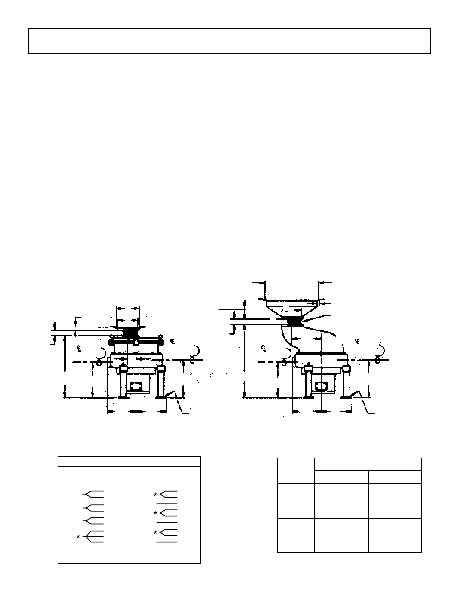
INSTALLATION DIAGRAM
MOTOR WIRING DIAGRAM
VOLTAGE-AMPERAGE TABLE
1” Min.
6” Max.
Cutout
1” Min.
6” Max.
10 1/2”
Disposer shown with regular 7” drum
and sink mounting assembly
Note: All dimensions shown at 0” foot height adjustment
8” length of neoprene connector sleeve
furnished. May be cut to desired length.
Adjustable 0” to 2”
Disposer shown with offset drum and
cone mounting assembly
Table Cutout
13” for 12” cone
16” for 15” cone
19” for 18” cone
1”
1”
10 1/4”
8”
12 1/2”
11”
1”
4 3/4” for 12” cone
5 1/2” for 15” cone
6 1/4” for 18” cone
10 1/4”
11”
Adjustable 0” to 2”
13 1/2”
22 1/2”
(26 1/2”)
12 1/2”
7”
8”
Water
inlet
Drain
Drain
Water
inlet
13 1/2”
27”
HP
THREE PHASE
Volts
Amps*
7 1/2
208
230
460
23.0
22.0
6.8
10
208
230
460
33.0
30.0
15.0
*Ratings are for 60 Hz operation.