Standard insinkerator mountings – InSinkErator SS-50 User Manual
Page 5
5
Standard InSinkErator Mountings
#5 MOUNTING ASSEMBLY
Follow these instructions to install a #5 sink flange to a
standard 3-1/2 to 4 inch sink opening.
1. Unscrew the three backup screws (6) until they are
flush with the upper mounting flange (5) surface. Pry
the retainer ring (7) free from the strainer flange (2)
with a screwdriver and separate all mounting
assembly parts (2-7).
2. Form a 3/4" thick ring of top grade oil base putty
around the sink opening (use a non-hardening putty).
Insert the strainer flange (2) into the sink opening and
press firmly in place. Clean away any excess putty.
3. From underneath the sink, place the strainer flange
gasket (3), back up flange (4) - flat side up, and upper
mounting flange (5) over the strainer flange and hold
them up to the sink. Snap the retainer ring (7) into the
groove on the strainer flange to hold the mounting
parts in place.
4. Tighten the three backup screws evenly until the
backup flange draws snugly against the underside
of the sink and the strainer flange is held securely
in place.
5. Place the body flange (9 - lugs upward) over the lip of
the mounting flange (10) and fit the mounting
gasket (8) onto the lip.
6. Place the mounting gasket (11) on the disposer body
flange. Secure the mounting flange (10) to the
disposer body flange with six screws (12) provided.
7. Raise the disposer to the upper mounting flange (5)
so the body flange (9) is positioned with the lugs to
the right of the screws.
8. While supporting the disposer, turn the body flange
(9) to the right until all three lugs are engaged in the
mounting flange (5). Swivel the disposer to align the
discharge outlet with the drain tap. The disposer can
be turned 360 degrees.
9. Align the disposer to the plumbing connection and
insert the service wrench into the left side of a lug
and continue to turn the body flange to the right
(approximately one quarter turn) until it locks onto the
notches on the upper mounting flange.
NOTE: Special mounting instructions are included in the
#5 Short Mounting Kit.
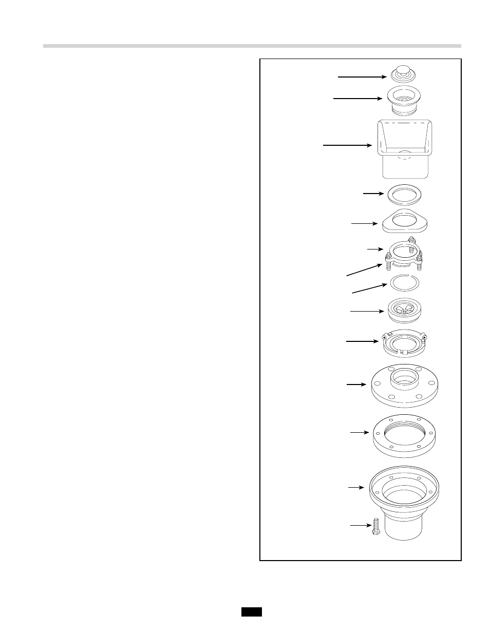
Figure 3. #5 Mounting Assembly
(1) Stopper
(2) Strainer Flange
Sink*
(3) Strainer Flange Gasket
(4) Backup Flange
(5) Upper Mounting Flange
(6) Backup Screw
(7) Retaining Ring
(8) Mounting Ring
(9) Body Flange
(10) Mounting Flange
(11) Mounting Gasket
Disposer Body Flange*
(12) 1/4" Screw
* Not included as part of #5 mounting