2 method 2: a low profile molded-in detail – Interlink Electronics Micro Joystick User Manual
Page 11
www.interlinkelectronics.com
9
MicroJoystick
Integration Guide
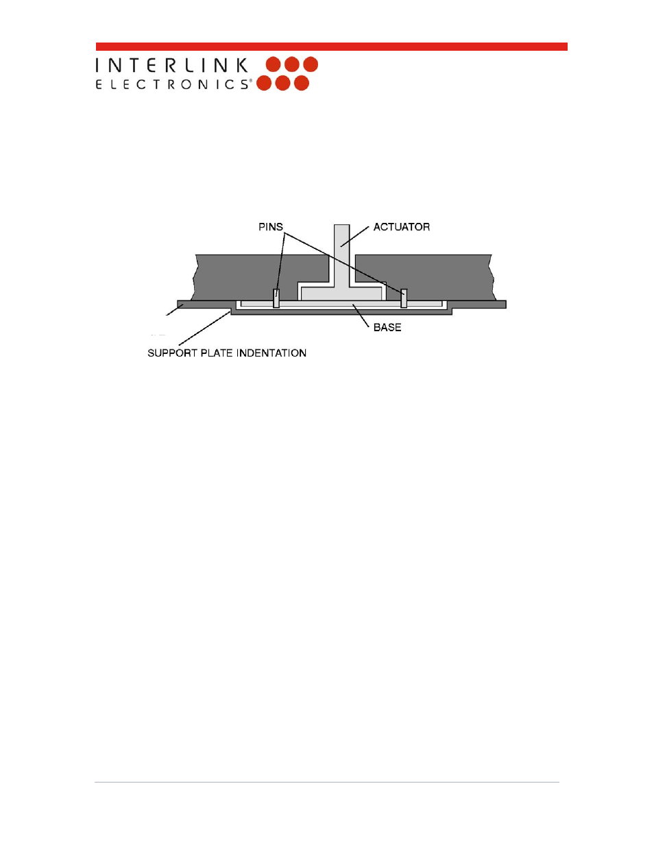
5.1.2 Method 2: A low profile molded-in detail
If the depth of the detail in section 5.1.1 is too great, a low-profile detail can be used in
conjunction with a special support plate to mount the MicroJoystick as shown in the illustration
below. As in section 5.1.1, either a close-tolerance fit around the MicroJoysticks captuator or pins
can be used to register the MicroJoystick in the detail. The sketch below illustrates pins being
used to register the MicroJoystick in the low-profile detail.
The support plate has an indentation in it to capture the MicroJoystick’s base. The thickness of
the indentation is slightly thicker than the thickness of the MicroJoystick’s base. This prevents
unwanted forces from being applied to the MicroJoystick that could cause unwanted cursor drift.
The support plate should be flat and free from surface defects (e.g., bumps), and can be
integrated into the backplate of a keyboard or can be constructed as a separate metal or plastic
unit.
To install the MicroJoystick, simply…
Drop the MicroJoystick into the detail
Register the MicroJoystick around the captuator or on the pins
Check to make sure the MicroJoystick is positioned correctly
Install the support plate.
Please see Figure 3, “Using Self Tapping Screw with Indented Support Metal Plate.”
SUPPORT PLATE