Interlink Electronics Micro Joystick User Manual
Page 13
www.interlinkelectronics.com
11
MicroJoystick
Integration Guide
5.1.3
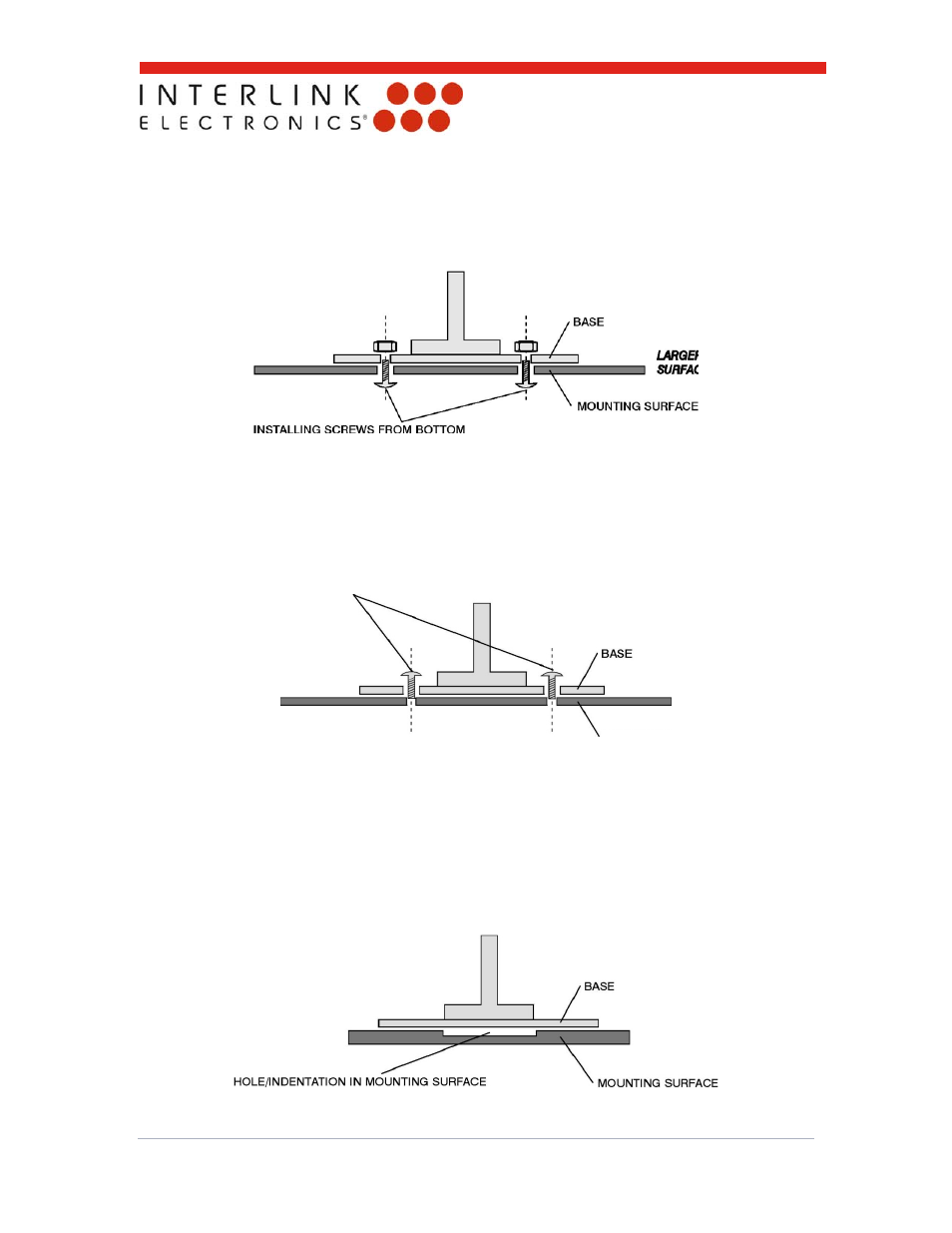
Method 3: Mounting the MicroJoystick to a flat surface
The illustration below shows how the MicroJoystick can be mounted to a flat surface such as a
PCB or molded keyboard housing.
The holes in the mounting surface should be designed as clearance holes (e.g., larger than the
thread diameter of the screws). This helps to ensure that the screws only thread into one surface
-- the MicroJoystick’s base. If the screws thread into both the MicroJoystick’s base and the
mounting surface, the resultant stress could cause cursor drift. Alternatively, the screws can be
installed from the top of the MicroJoystick as shown in the illustration below.
When installing screws from the top of the MicroJoystick, the holes in the MicroJoysticks base are
clearance holes. The screws should only thread into the mounting surface. If the holes in the
MicroJoystick are too small, they may be drilled out and enlarged.
The mounting surface must be flat to within 0.013mm. Bowing of the mounting surface or surface
bumps can cause preloads on the MicroJoystick resulting in unwanted cursor movement. To help
reduce the effects that any existent bumps or bowing may have a hole or indentation 12.7mm to
15.2mm in diameter can be machined or molded into the mounting surface as shown below.
LARGER OPENING IN MOUNTING
SURFACE THAN IN BASE
INSTALLING SCREWS
FROM TOP
MOUNTING SURFACE
LARGER OPENING IN BASE
THAN IN MOUNTING SURFACE