1 mounting methods – Interlink Electronics Micro Joystick User Manual
Page 9
www.interlinkelectronics.com
7
MicroJoystick
Integration Guide
5.1 Mounting
Methods
Several different mounting methods are detailed in the following section. Before designing a
mounting method for the MicroJoystick, please carefully review all of the suggested mounting
methods and design parameters. This will enable you to design the best mounting method
for your system, reduce time to production, and help optimize your installation procedure.
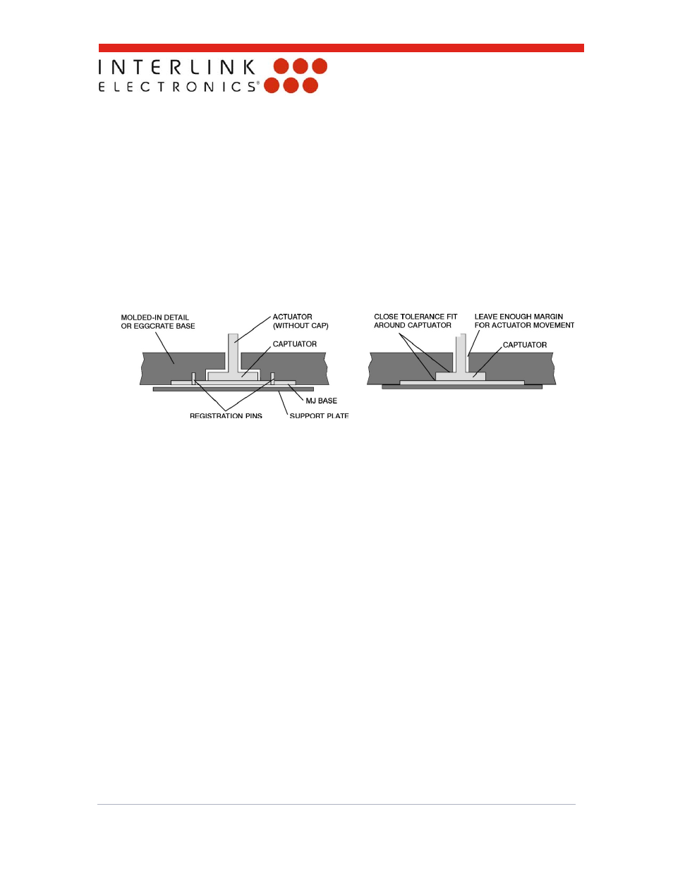
5.1.1 Method 1: A molded-in detail
A simple molded-in detail can be used to mount the MicroJoystick. This method is ideal for
integration of the MicroJoystick in-between keyboard key caps (i.e., the detail can be molded
directly into the keyboard’s base, eliminating or reducing incremental system costs). Either
pins or a close-tolerance fit around the MicroJoystick’s captuator can be used to register the
MicroJoystick in the detail as shown in the illustrations below.
Registering with Pin
Registering by the Captuator
The portion of the molded-in detail that holds the MicroJoystick’s base is designed to be
slightly thicker than the thickness of the MicroJoystick’s base. This helps prevent
unwanted forces from being applied to the MicroJoystick. Since the MicroJoystick is
designed for maximum sensitivity, forces as small as 20 grams can cause cursor move-
ment or cursor “drift.” The term “drift” is used to describe cursor movement caused by
unwanted force permanently applied to the FSR in the mounting process.
A support plate is used to keep the MicroJoystick in place. The support plate should be
flat and free from surface defects (e.g., bumps). The support plate can be the backplate
of a keyboard or can be constructed as a separate metal or plastic unit.
To install the MicroJoystick, simply…
Drop the MicroJoystick into the detail
Register the MicroJoystick around the captuator or on the pins
Check to make sure the MicroJoystick is positioned correctly
Install the support plate.
Please see Figure 2, “Using Pin in Top Plate for Registration with Support Bosses at
Bottom.”