Interlink Electronics FSLP Sensor User Manual
Page 5
www.interlinkelectronics.com
3
Force Sensing Linear Potentiometer (FSLP)
Integration Guide
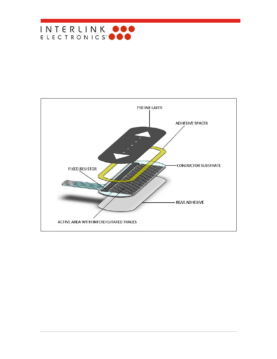
Like the basic single-zone FSR, the Interlink Electronics FSLP has an FSR ink layer and a
conductor substrate layer separated by an adhesive spacer. The FSLP’s conductor layer
however, is not simply a set of interdigitated silver fingers; it consists of two drive lines connected
to either end of a printed fixed resistor and a sense line. Silver fingers orthogonally protrude along
the entire length of the fixed resistor. These silver fingers are interdigitated with the sense line.
When the FSR ink and conductor membranes are pressed together, the sense line is shorted to a
point along the fixed resistor through the orthogonally protruding fingers. The resistance from
either drive line to the touch point is proportional to the location of the touch along the length of
the fixed resistor.
Figure 2: Exploded view of the FSLP.