Interlink Electronics FSLP Sensor User Manual
Page 6
www.interlinkelectronics.com
4
Force Sensing Linear Potentiometer (FSLP)
Integration Guide
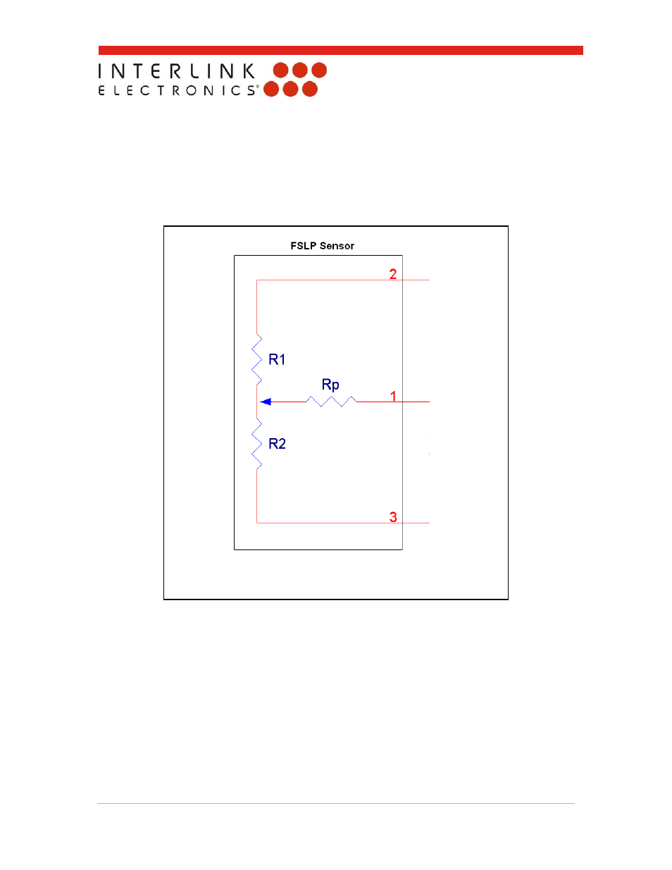
Figure 3 shows a schematic view of the sensor. Notice that the sensor is a three-terminal device
and when touched, has a circuit that is equivalent to three resistors. R1 is the resistance from
sensor terminal 2 to the touch spot. R2 is the resistance from the touch spot down to sensor
terminal 3. Rp is connected to the junction between R1 and R2 by the user’s touch. As the user
varies the touch spot from the top of the sensor to the bottom of the sensor, R1 becomes larger
and R2 becomes smaller. As the user presses harder, Rp decreases. Rp varies from around
300kΩ at very light touches to 2kΩ at extremely heavy touches. The resistance is roughly
proportional to the reciprocal of the force.
Figure 3: Schematic representation of the FSLP.