0 mounting and connection, 1 mounting, 2 fslp types – Interlink Electronics FSLP Sensor User Manual
Page 7
www.interlinkelectronics.com
5
Force Sensing Linear Potentiometer (FSLP)
Integration Guide
4.0 Mounting and Connection
4.1 Mounting
There are a few critical elements to consider when mounting the FSLP:
The mounting surface should be free of any raised features (e.g. copper traces on a PCB
or dust contamination) as they will interfere with the sensor’s proper operation.
If the sensor is being mounted to a PCB, it should be installed after PCB assembly is
complete. Heat generated during the soldering of components can damage the FSR.
When laminating the sensor, be sure to use a hard roller or other depression tool to
ensure proper bonding of the sensor’s pressure-sensitive adhesive and the removal of
any air bubbles.
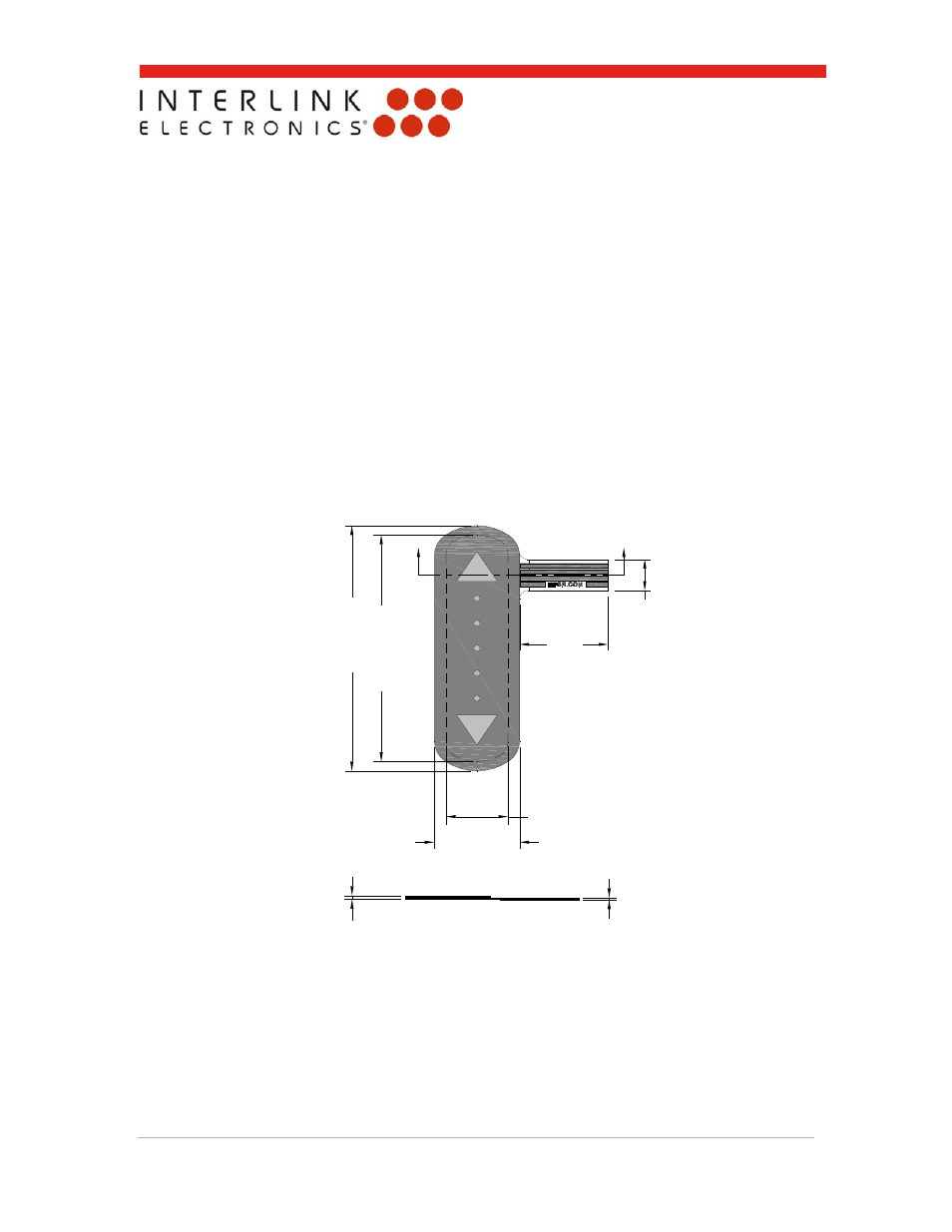
4.2 FSLP
Types
39
.3
±
0
.1
0
13.5±0.10
36.
3
(A
CTIV
E AR
EA
)
14.0
5.0
9.8
(ACTIVE AREA)
T=0.61
±
0
.0
6
0.34±0.04
A
A
Figure 4: Overall dimensions of the standard FSLP. All dimensions are in millimeters.