James Loudspeaker M1000 User Manual
Page 7
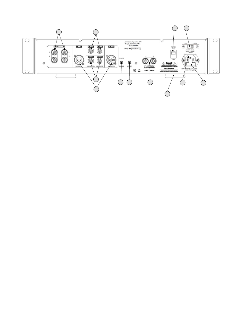
REAR PANEL
10
Left/right high level inputs - for connecting high level speaker outputs from another amplifier to drive the
subwoofer amplifier. Useful for zones where only stereo left/right high level speaker signals are available and a
subwoofer needs to be added.
11
Left/right RCA inputs - For feeding line-level stereo left/right signals. Also, either left or right RCA jack can
be used for a mono LFE input.
12
Left/right XLR balanced inputs - For feeding BALANCED line-level stereo left/right signals. Also, either left
or right XLR jack can be used for a mono LFE input.
13
Left/right RCA outputs - For looping the subwoofer input signal to additional amplifiers. The signal
received by the RCA or XLR inputs is passed out through these jacks and is not effected by the amplifier and
maintains left/right separation. XLR BALANCED inputs are converted to unbalanced RCA output.
14
12V trigger input (3.5mm) - For triggering the power on/off from other devices such as processors or
receivers that have a 12V trigger output. 6V minimum required for triggering.
NOTE: Once in trigger mode, the amplifier cannot be turned on without a 12V trigger signal. To disable the 12V
trigger, turn the unit off, then hold down the left and right navigation buttons while turning the amplifier on with
the rear power switch. The trigger mode will be turned off and the amplifier will power on.
15
External IR input (3.5mm) - For attaching an external IR receiver. Plugging in an IR receiver here will
disable the font panel IR receiver.
16
Speaker 5-way binding posts - Connect your loudspeaker here. Minimum impedance of the load is 4
ohms. Multiple woofers can be connected if the combined load impedance is 4 ohms or greater.
17
Power Switch - Turns the amplifier on or off. Amplifier must be on for the trigger or auto sense modes to
operate.
18
115V/230V AC mains voltage selector - For switching the operation for 110V-120V, 60Hz or 220V-240V,
50Hz AC line voltages. NOTE: when the AC line voltage is changed, the fuse must also be changed to
continue to provide protection to the amplifier.
19
IEC Power cable connector - Connect a IEC AC cable here rated for 15A service.
20
Fuse holder - The fuse holder is part of the IEC connector. Use a GDA type fuse as follows: 15A for 115V
operation and 8A for 230V operation.
21
Removable feet - The amplifier feet can be removed as required for rack mount installation.
18
10
11
12
13
14 15
16
17
19
20
21
Page 7