JIMS Box 2 1208-1352 (all models of 120, 131, or 135 Alpha, Beta and Evo Mount Engines) User Manual
Page 13
555 Dawson Drive, Camarillo, CA 93012 Phone 805-482-6913 • Fax 805-482-7422
12
Rev I
8-12
No.1208-1352
A Division of Thiessen Products, INC
IIn
ns
st
tr
ru
uc
ct
tiio
on
n S
Sh
he
ee
et
t F
Fo
or
r B
Bo
ox
x 2
2 1
12
20
0”
”,, 1
13
31
1”
” o
or
r 1
13
35
5”
”
E
En
ng
giin
ne
e A
As
ss
se
em
mb
bl
liie
es
s O
Or
r E
En
ng
giin
ne
e R
Ra
ac
ce
e K
Kiit
ts
s
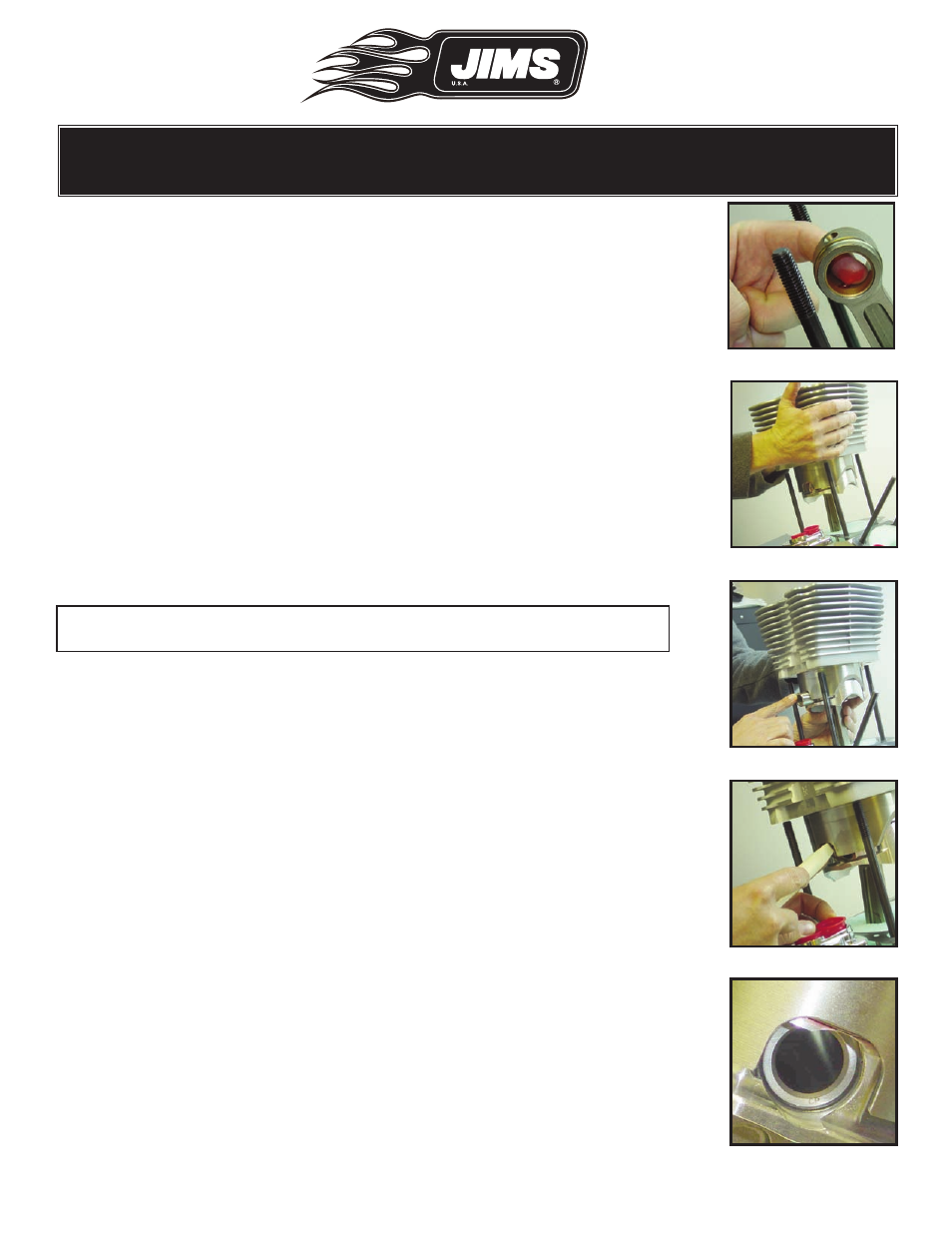
•
Lubricate the wrist pin bushing with assembly lube. See Fig.47.
•
Carefully position the cylinder over the rear studs so the short fins are
on the right, toward you. The spigot bevel will be toward the front of
the engine. See Fig. 48.
CAUTION: Be careful not to scratch the base gasket sealing surface on the
bottom with the cylinder studs during assembly. Be careful not
to bend the cylinder studs during cylinder installation.
•
Lower the cylinder assembly over the studs while guiding the rod into
the piston.
•
Align the wrist pin with the wrist pin bushing.
•
Slide the pin through the rod until it is stopped by the left, far piston
pin clip. See Fig. 49.
•
Install the remaining pin clip. Start one end of the clip into the wrist pin
hole. Use a hard plastic rod, or wooden dowel to work the clip fully into
its groove.
Note: Be sure to wear your safety glasses when installing wrist pin clips.
See Fig. 50.
•
Verify the clip is fully seated in its groove. See Fig. 51.
Important: Be very careful not to gouge, nick, dent or otherwise deform
the corners of the wrist pin hole.
•
Remove the material protecting the case bore.
•
Apply a thin film of the supplied assembly lube to the front and back of
the piston skirt.
•
Inspect the mating surfaces of the base gasket and cylinder to be sure
they are clean.
•
Gently slide the cylinder down until it seats on the base gasket.
•
The base gasket normally has a little curl so check that the gasket is
located on the dowels as you lower the cylinder into position.
Fig.47 - Lube rod pin bushing
Fig.48 - Assistant holds assy.
Fig.49 - Insert wrist pin
Fig.50 - Insert ring clip
Fig.51 - Verify fully seated