JIMS Box 2 1208-1352 (all models of 120, 131, or 135 Alpha, Beta and Evo Mount Engines) User Manual
Page 16
555 Dawson Drive, Camarillo, CA 93012 Phone 805-482-6913 • Fax 805-482-7422
15
Rev I
8-12
No.1208-1352
A Division of Thiessen Products, INC
IIn
ns
st
tr
ru
uc
ct
tiio
on
n S
Sh
he
ee
et
t F
Fo
or
r B
Bo
ox
x 2
2 1
12
20
0”
”,, 1
13
31
1”
” o
or
r 1
13
35
5”
”
E
En
ng
giin
ne
e A
As
ss
se
em
mb
bl
liie
es
s O
Or
r E
En
ng
giin
ne
e R
Ra
ac
ce
e K
Kiit
ts
s
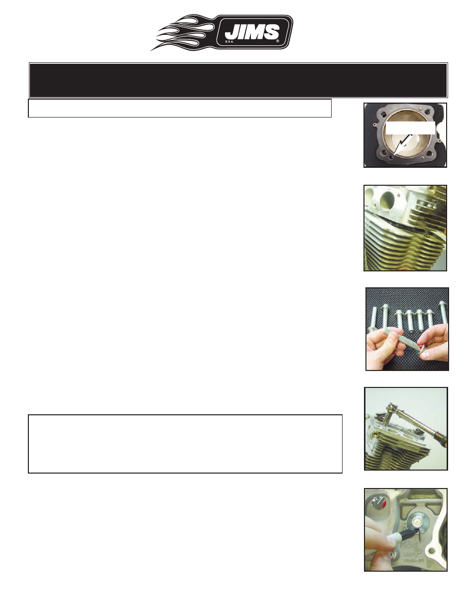
Note: Do not allow any lube to contact the gasket or gasket surfaces.
• Select a head and place it over the locating dowels and onto the cylin-
der.
• Be sure the head gasket is properly placed. See Fig. 63.
Head orientation: See Fig. 66.
• The Screamin’ Eagle
®
logo goes to the right of the engine.
• The pushrod holes go to the right of the engine.
• The intake port goes toward the center of the engine.
• Make sure the head is fully seated on the cylinder.
• Lay out the head bolts within easy reach: two short and two long bolts
are used for each head.
• Lightly lubricate, with copper anti seize lube, the internal threads of
each bolt.
• Lightly lubricate, with copper anti seize lube, the underside of each
head bolt flange. See Fig. 64.
• This is the flat area under the bolt head that contacts the cylinder head.
• Thread the two short bolts into the stud holes on the left (spark plug)
side of the head.
• Thread the remaining longer bolts into the other two
• Gently snug all four bolts (finger tight).
• Repeat step on page 14. See “Very Important Note” to install the
remaining head.
• Remember to align the hole in the gasket with the cylinder’s oil drain
hole.
Cylinder Head Torque. See Fig. 65.
Note: Follow the tightening sequence exactly as it is described below.
Deviation from the procedure can result in gasket failure, or severe
damage to the heads and cylinders. If you have any questions
regarding the torque sequence please contact JIMS Tech Support at
(805-482-6913). See Fig. 66 (Pg. 17)
• After all head bolts are finger tight, follow the sequence in Fig. 66
(Pg.17) to torque the heads as described below with a 1/2” 12 point
deep socket.
• Torque each lubed head bolt to 8 ft/lbs, following the sequence in
Fig. 66.
• Continuing in the same sequence, torque each bolt to 18 ft/lbs.
• With a grease pencil or similar marker, mark a line on the smooth
surface of all 8 head bolts, continuing this line down to the head
casting surface, as pictured in Fig. 67.
Fig.62 - Gasket alignment
Fig.63 Verify gasket alignment
Fig.64 - Moly lube
Fig.65 - Follow torque specs
Fig.67 Mark bolt and head
Drain Hole