JIMS Box 2 1208-1352 (all models of 120, 131, or 135 Alpha, Beta and Evo Mount Engines) User Manual
Page 5
555 Dawson Drive, Camarillo, CA 93012 Phone 805-482-6913 • Fax 805-482-7422
4
Rev I
8-12
No.1208-1352
A Division of Thiessen Products, INC
IIn
ns
st
tr
ru
uc
ct
tiio
on
n S
Sh
he
ee
et
t F
Fo
or
r B
Bo
ox
x 2
2 1
12
20
0”
”,, 1
13
31
1”
” o
or
r 1
13
35
5”
”
E
En
ng
giin
ne
e A
As
ss
se
em
mb
bl
liie
es
s O
Or
r E
En
ng
giin
ne
e R
Ra
ac
ce
e K
Kiit
ts
s
• Place a cylinder on the bench, top end up.
• The cylinder’s bore should be clean to the touch and lightly oiled.
See Fig. 10.
End Gap Measurement See Fig. 11.
• Piston Ring end gap range:
• Top ring: .017” to .022”
• Second ring: .022” to .030”
• Oil control rails: .015” to .030”
• Record your end gap measurements in the chart on page below. Tilt and
start a piston ring into the bore. The most common and perhaps easiest way
to do this is to first insert the side of the ring opposite the gap. Then, flex
each ring end into the bore. Use your fingers to control twist as you insert
the ring. See Fig. 12.
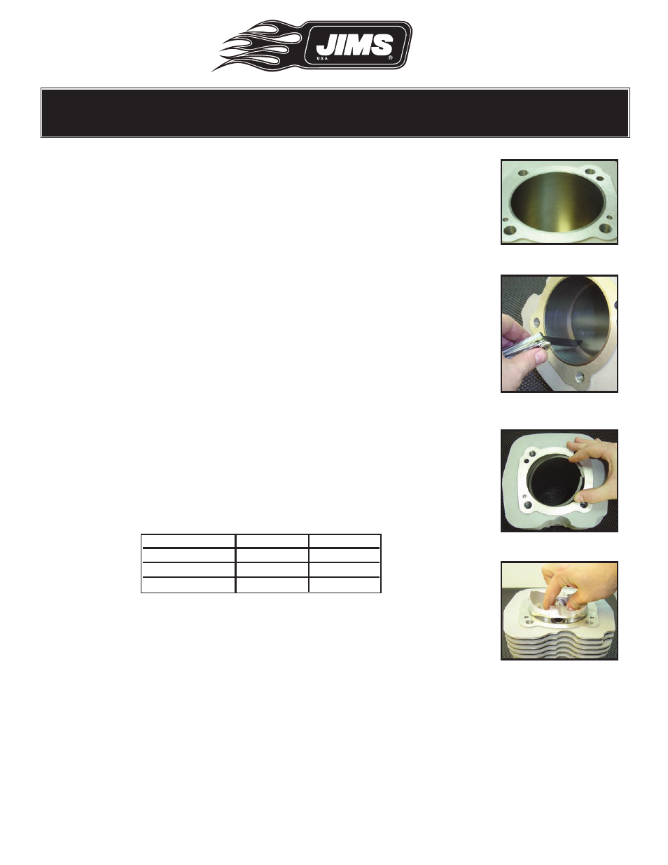
• When the ring is in the bore, use the piston to force it down the bore until
the piston pin is slightly below the top of the cylinder. See Fig. 13.
• Remove the piston.
• The piston ring is now square with the bore and positioned for end gap
inspection.
• Use a feeler gage as pictured to measure the width of the gap. You may
stack two blades if necessary. See Fig. 11.
• Remove each ring by hooking it with a finger on the side opposite the gap
and pulling smoothly and gently out of the cylinder bore.
• Start measuring with all piston rings to one side of the cylinder.
• After each ring is checked:
• Place rings having passed the end gap test on the opposite side of the cylin-
der.
• Place each of those failing the end gap test on a piece of paper and write
their measured end gap on the paper.
• When you have finished, separate and cover the piston rings not requiring
additional fitting.
Fig.10 - Clean cylinder bore
Fig.12 - Carefully twist in
Fig.11 - Feeler gauge gap
Fig.13 - Press ring down
Front Piston Rear Piston
Top Ring
Second Ring
Oil Control Rails