Control elements – LD Systems LAX 6 D User Manual
Page 9
9
IT
ALIANO
POLSKI
ESP
AÑOL
FRANCAIS
FRANCAIS
FRANCAIS
FRANCAIS
FRANCAIS
DEUTSCH
ENGLISH
7
AUX
This control is used to adjust the level of the signal sent to the AUX path. Please note that this is a "post fader"
path, i.e., the level of the signal sent to the AUX path is influenced by the level knob of the respective channel.
With the LAX6D, it is not only possible to route the signal to an external effects processor or the like in this man-
ner, but also to the integral effects module.
8
PAN
The mono channels of the LAX6/LAX6D have panorama (PAN) controls and the stereo channels have balance
(BAL) controls, both of which are used to distribute the signal to the right and left output channels.
9
PEAK LED
All channels of the LAX6/LAX6D are equipped with a peak LED for monitoring the respective audio signal. If the peak LED
lights up (6 dB below the actual clipping threshold), this means that the signal is peaking and distortion may ensue.
10
LEVEL CONTROL
This knob controls the overall volume of the respective channel, i.e., the level at which the signal is sent to the main mix.
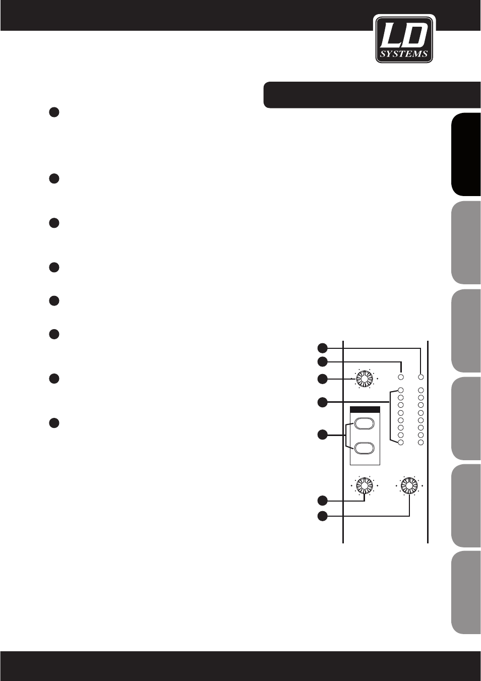
11
MAIN MIX LEVEL
This knob is used to control the level of the signal sent to the MAIN MIX and recording (TAPE OUT) outputs.
12
PHONES/CONTROL ROOM
This control is used to adjust the level of the signal sent to the
PHONES/CONTROL ROOM output.
13
LED LEVER METER
The stereo level meter (8 segments) is used to monitor the level of the signal
sent to the PHONES/CONTROL ROOM output.
14
2-TRACK PATH
When the 2TK TO CONTROL ROOM button is pushed, the 2-TRACK IN signal
is sent directly to the CONTROL ROOM output; the level is adjusted using the
PHONES/CONTROL ROOM control.. When the 2TK TO MIX MIX button is
pushed, the 2-TRACK IN signal is sent directly to the MAIN MIX output; the
level is adjusted using the MAIN MIX LEVEL control.
Note: Both buttons can also be pressed simultaneously, so that the 2-TRACK
signal is sent to both the control room output and the main mix out; the
corresponding level is adjusted using the associated controls.
CONTROL ELEMENTS:
0
+15
8
-
0
+15
8
-
0
+15
8
-
-18
-12
-24
-6
CLIP
+6
0
+12
CONTROL ROOM
PHONES/
LEVEL
MAIN MIX
MAIN MIX
CONTROL ROOM
OUTPUT LEVEL
LR
PWR
PHANTOM
2TK TO
AUX RETURN
11
12
13
14
15
16
17