Ls-aes – Lynx Studio LS-AES User Manual
Page 10
LS-AES
Page 8
Digital I/O Panel Description
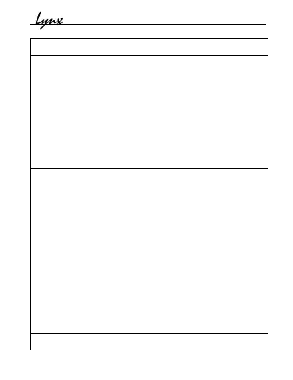
Digital Format
Selects AES/EBU or S/PDIF formats. This control affects the electrical
characteristics and channel status protocol on the digital input and output
SRC Mode
Selects the sample rate converter mode:
On - The sample rate converter is enabled on the digital input. The sample
rate of the digital input signal is converted to the current rate selected for
the host card and LS-AES. Bit-perfect digital transfers are not possible in
this mode. This is the default mode. Use this mode when connecting to
external equipment that is not synchronized to the LS-AES.
Off - The sample rate converter is disabled. In this mode, the digital input
signal must be synchronous to the clock source driving the host card and
LS-AES in order to prevent signal errors. Digital input data is transferred
bit-perfect. Use this mode when connecting to external devices that are
locked to a clock source that is common to the LS-AES or host card. This
mode is also valid if the digital input is selected as the clock source for the
LS-AES.
On: Digital Out – The sample rate converter is enabled on the digital output.
The sample rate of the digital output signal is converted to the sample rate
received on the corresponding digital input.
SRC Ratio
Indicates the sample rate conversion ratio in either of SRC On modes.
Digital In
Mode
Indicates either Professional or Consumer digital input status. Professional
status is generally associated with an AES/EBU signal, and consumer status is
generally associated with an S/PDIF signal.
Digital In
Status
Indicators
Indicates various digital inputs status:
Lock – Red: receiver PLL not locked, Green: receiver PLL locked
Validity – Green: channel status validity bit set
Copyright – Green: SCMS copyright bit set, consumer mode only
Original – Green: SCMS original bit set, consumer mode only
Non Audio – Green: channel status non-audio bit set. Typically set when
non-PCM data is received, e.g. Dolby Digital, DTS
Parity – Red: parity error detected
Confidence – Red: signal quality degraded
Biphase – Red: bi-phase coding error detected
CS CRC – Red: channel status CRC error detected
Q CRC – Red: subcode data CRC detected
Digital Out
Valid
Sets the validity bit in the digital output channel status.
Digital Out
Non-Audio
Sets the non-audio bit in the digital output channel status. This bit must be set
when transmitting non-PCM data such as Dolby Digital and DTS.
Digital Out
Emphasis
Sets the emphasis bit in the digital output channel status.