Marantz AV8003 User Manual
Page 16
SETUP
BASIC
OPERA
TION
ADV
ANCED
OPERA
TION
REMOTE
CONTROLLER
TROUBLESHOOTING
OTHERS
NAMES AND
FUNCTION
CONNECTIONS
ENGLISH
12
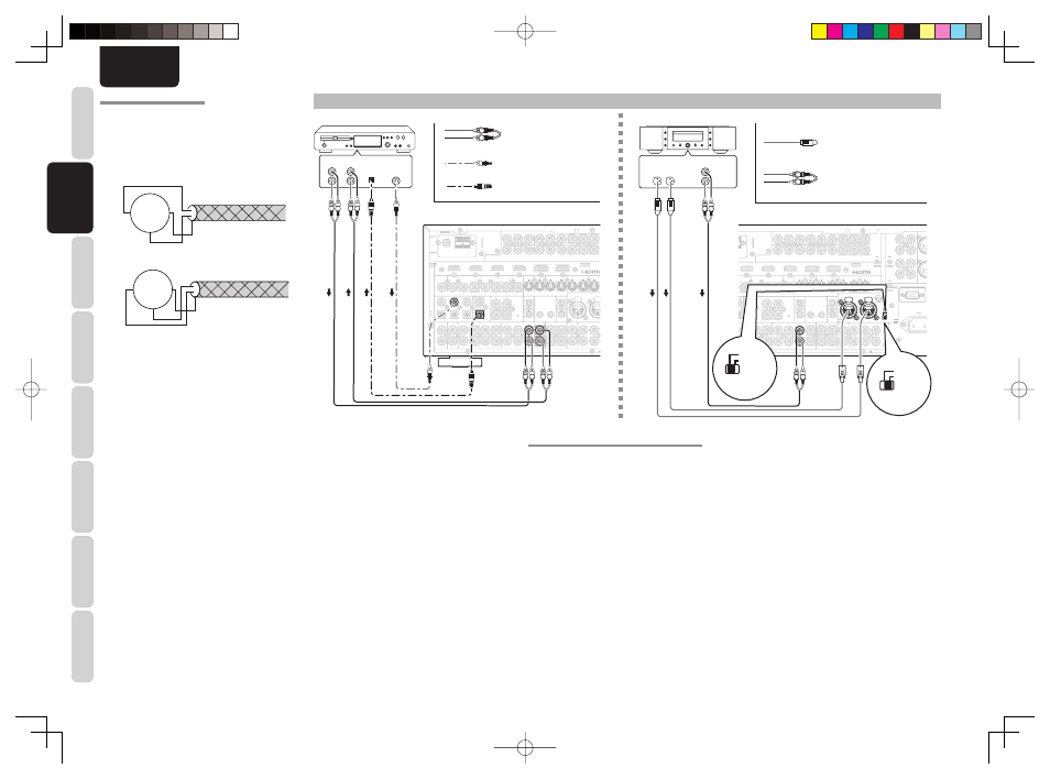
CONNECTING AUDIO COMPONENTS
PUSH
PUSH
3
2
3
1
2
FM
FM (
(75
75
Ω
Ω))
GND
GND
AM
AM
ANTENNA
ANTENNA
OUT
PUT
1
OUT
PUT
2
INPUT 3
INPUT 3((VCR1
VCR1))
OUTPUT 1
OUTPUT 1
OUTPUT 2
OUTPUT 2
INPUT 1
INPUT 1(
(TV
TV)
)
INPUT 4
INPUT 4((DSS/VCR2
DSS/VCR2))
INPUT 2
INPUT 2(
(DVD
DVD)
)
COMPONENT
COMPONENT
VIDEO
VIDEO
C
CB
B//P
PB
B
C
CR
R//P
PR
R
C
CR
R//P
PR
R
C
CR
R//P
PR
R
C
CB
B//P
PB
B
C
CB
B//P
PB
B
Y
Y
Y
Y
Y
Y
INPUT 1
INPUT 1(
(TV
TV)
)
INPUT 4
INPUT 4(
(DSS
DSS // VCR2
VCR2)
)
INPUT 3
INPUT 3(
(VCR1
VCR1)
)
INPUT 2
INPUT 2((DVD
DVD))
IN
IN
OUT
OUT
IN
IN
OUT
OUT
OUT
OUT
IN
IN
IN
IN
OUT
OUT
MONITOR
MONITOR
OUT
OUT
DVD
DVD(
(2
2)
)
DSS/VCR2
DSS/VCR2(
(4
4)
)
TV
TV(
(1
1)
)
ZONE
ZONE
OUT
OUT
VCR1
VCR1(
(3
3)
)
DVD
DVD((2
2))
DSS/VCR2
DSS/VCR2(
(4
4)
)
VCR1
VCR1(
(3
3)
)
TV
TV(
(1
1)
)
MONI. O
MONI. OUT
2
2
1
1
FLASHER
FLASHER
IN
IN
IR
IR
RECEIVER
RECEIVER
IN
IN
6
6
COAX.
COAX.
5
5
4
4
OUT
OUT
IN
IN
1
1
2
2
EMITTER
EMITTER
OUT
OUT
DC OUT
DC OUT
DIGITAL IN
DIGITAL IN
DIGITAL OUT
DIGITAL OUT
MAIN
MAIN
ZONE
ZONE
R
R
L
L
REMOTE
REMOTE
CD/CDR BALANCED I
CD/CDR BALANCED IN
OUT
OUT
R
R
OUT
OUT
L
L
TAPE
TAPE
CD/CDR
CD/CDR
OUT
OUT
IN
IN
IN
IN
R
R
OUT
OUT
L
L
DSS/VCR2
DSS/VCR2
AUDIO
AUDIO
TV
TV
IN
IN
SR
SR
VCR1
VCR1
IN
IN
DVD
DVD
SL
SL
SBR
SBR
SBL
SBL
A
A
B
B
(
(AUX
AUX)
)
3
3
2
2
1
1
OPT.
OPT.
VIDEO
VIDEO
S-VIDEO
S-VIDEO
ZONE OUT
ZONE OUT
5
5
DIGITAL IN
DIGITAL IN
DIGITAL OUT
DIGITAL OUT
AUDIO
AUDIO
OPT.
OPT.
R
R
L
L
OUT
OUT
CD/CDR
CD/CDR
IN
IN
ANALOG
INPUT
ANALOG
OUTPUT
L
R
L
R
DIGITAL
INPUT
DIGITAL
OUTPUT
R L
R L
R L
R L
L
R
The output audio signal from the TAPE OUT jack and
the CD/CD RECORDER OUT jack is the same signal
which is currently selected.
Caution:
• Do not connect this unit and other components
to mains power until all connections between
components have been completed.
Notes:
• Insert all plugs and connectors securely. Incomplete
connections may make noise.
• Be sure to connect the left and right channels
properly.
Red connectors are for the R (right) channel, and
white connectors are for the L (left) channel.
• Be sure to connect input and output properly.
• Refer to the instructions for each component that is
connected to this unit.
• Do not bind audio/video connection cables with
power cords and speaker cables this will result in
generating a hum or other noise.
CONNECTING DIGITAL AUDIO COMPONENTS
• There are 6 digital inputs, 3 coaxial jacks and
3 optical jacks, on the rear panel. You can use
these jacks to input PCM, Dolby Digital and DTS
bitstream signals from a CD, DVD, or other digital
source components.
• There is one digital output coaxial jack and one
optical output jack on the rear panel. These jacks
can be connected to a CD recorder, or a MD deck
inputs, respectively.
• Refer to the instructions for each component. To
setup the digital audio format of DVD player, or
other digital source’s connected to digital input
jacks.
• Use fi ber optical cables (optical) for DIG-1,2,3
input jacks. Use 75 ohms coaxial cables (for digital
audio or video) for DIG-4, 5, 6 input jacks.
• You can designate the input for each digital input/
output jacks according to your component. See
page 23.
CD recorder
Analog Audio
Digital Audio (coaxial)
Notes:
• There is no Dolby Digital RF input jack. Use an
external RF demodulator Dolby Digital decoder
when connecting the Dolby Digital RF output jack
of the videodisc player to the digital input jack.
• The digital signal jacks on this unit conform to
the EIA standard. If you use a cable that does not
conform to this standard, this unit may not function
properly.
• Each type of audio jack works independently.
Signals input through the digital and analog jacks are
output through the corresponding digital and analog
jacks, respectively.
ABOUT BALANCED JACKS
• The balanced output connector uses a XLR
connector.
• The XLR connector for professional use is internally
wired in either of the following two systems.
1.
European system
(Pin
w
= HOT, Pin
e
= COLD)
w q
e
GND
COLD
HOT
2.
USA system (Pin
w
= COLD, Pin
e
= HOT)
w q
e
GND
HOT
COLD
• This unit uses the 1. European system.
When a preamp or main amplifi er adopting the
European system is connected using a cable with
XLR balanced connectors, the reproduced signal
may be inverted of phase.
Digital Audio (optical)
1
1
PUSH
PUSH
3
1
2
3
1
2
R
R
R
R
SR
SR
SL
SL
SW
SW
C
C
SBR
SBR
SBL
SBL
L
L
SB
SBR
M
AM
OUT
OUT
PUT
PUT
1
1
OUT
OUT
PUT
PUT
2
2
INPUT 3
INPUT 3((VCR1
VCR1))
OUTPUT 1
OUTPUT 1
OUTPUT 2
OUTPUT 2
INPUT 4
INPUT 4((DSS/VCR2
DSS/VCR2))
NPUT 2
INPUT 2(
(DVD
DVD)
)
COMPONENT
COMPONENT
VIDEO
VIDEO
C
CB
B//P
PB
B
C
CR
R//P
PR
R
C
CR
R//P
PR
R
C
CR
R//P
PR
R
C
CB
B//P
PB
B
C
CB
B//P
PB
B
Y
Y
Y
Y
Y
Y
INPUT 1
INPUT 1(
(TV
TV)
)
INPUT 4
INPUT 4(
(DSS
DSS // VCR2
VCR2)
)
INPUT 3
INPUT 3(
(VCR1
VCR1)
)
INPUT 2
INPUT 2((DVD
DVD))
RS-232C
RS-232C
AC IN
AC IN
IN
IN
OUT
OUT
IN
IN
OUT
OUT
OUT
OUT
IN
IN
OUT
OUT
MONITOR
MONITOR
OUT
OUT
DSS/VCR2
DSS/VCR2(
(4
4)
)
ZONE
ZONE
OUT
OUT
R1
VCR1(
(3
3)
)
DVD
DVD((2
2))
DSS/VCR2
DSS/VCR2(
(4
4)
)
VCR1
VCR1(
(3
3)
)
TV
TV(
(1
1)
)
MONI. OUT
MONI. OUT
2
2
1
1
FLASHER
FLASHER
IN
IN
IR
IR
RECEIVER
RECEIVER
IN
IN
COAX.
COAX.
OUT
OUT
IN
IN
1
1
2
2
EMITTER
EMITTER
OUT
OUT
DC OUT
DC OUT
DIGITAL OUT
DIGITAL OUT
MAIN
MAIN
ZONE
ZONE
R
R
L
L
REMOTE
REMOTE
CD/CDR BALANCED IN
CD/CDR BALANCED IN
OUT
OUT
OUT
OUT
L
L
TAPE
TAPE
CD/CDR
CD/CDR
OUT
OUT
IN
IN
IN
IN
R
R
OUT
OUT
DSS/VCR2
DSS/VCR2
AUDIO
AUDIO
UNBALANCED
UNBALANCED
SR
SR
CR1
VCR1
IN
IN
SL
SL
SBR
SBR
SBL
SBL
SW
SW
C
C
A
A
B
B
7.1CH
7.1CH
IN
IN
(
(AUX
AUX)
)
OPT.
OPT.
BALANCED
BALANCED
UNBALANCED
UNBALANCED
S-VIDEO
S-VIDEO
ZONE OUT
ZONE OUT
SELECTOR
SELECTOR
1
2
3
CONNECTION
GND
HOT(+)
COLD(-)
3
2
1
R
R
L
L
CD/CDR IN
CD/CDR IN
AUDIO
AUDIO
PUSH
PUSH
3
1
2
3
1
2
BALANCED
BALANCED
UNBALANCED
UNBALANCED
SELECTOR
SELECTOR
IN
IN
CD/CDR
CD/CDR
L
R
L
R
R L
R L
L
R
BALANCED
UNBALANCED
BALANCED
BALANCED
UNBALANCED
UNBALANCED
SELECTOR
SELECTOR
BALANCED
BALANCED
UNBALANCED
UNBALANCED
SELECTOR
SELECTOR
Analog Audio (balanced)
Analog Audio (unbalanced)
Super Audio CD
Or
AV8003N.indb 12
AV8003N.indb 12
08.4.28 10:49:13 AM
08.4.28 10:49:13 AM