MBM Corporation 46 Installation User Manual
Page 7
Page 7 (13)
Art. nr 45961
Sep 2000
T09120
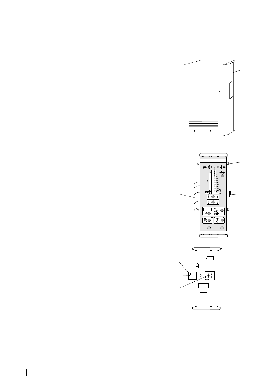
CHANGING PROCESSOR MODEL 306/310
CAUTION: Always handle the PCB, EEPROM, micro processor etc.
in accordance with electrostatic discharge procedures
(ESD). The PCB contains components that are sensitive
to ESD damage.
1.
Switch off the main power switch and disconnect the
power cord.
2.
Remove all sheet metal screws holding the front cover
(1) to the side frame.
3.
Lift off the cover.
4.
Disconnect the ribbon cable (2).
5.
Remove the four counter sunk screws (3) and remove
the front panel assembly.
6.
Remove the processor (5) using the extractor tool
(part No. 95147).
7.
Install the new processor (software version
PL90 M 1.00 or greater) by applying an even
pressure on the processor until it is fully inserted.
NOTE: On the socket under the processor there is an arrow
(7). Install the processor so that the arrow will be
pointing towards the small dent (6) on the processor.
8.
Mount the front panel assembly.
9.
Reset the EE prom by sliding DIP switch no.3 (4)
to its rightmost position.
10. Switch on the main power switch, wait app. 5
seconds until ”HEL” appears on the display. The
values in the EE prom is now erased.
11. Switch off the main power switch and slide DIP
switch no. 3 back to its leftmost position.
12. Switch on the main power switch. The Micro pro-
cessor will now load the EE prom with
the new values.
13. Switch off the main power switch and mount the
front cover.
1
1
2
3
4
5
6
7
8
9
10
Σ
1
2
3
4
5
VX
8 8 8
2
3
4
6
7
5