Understanding wavebook and wbk connectors, Wavebook/516e front panel, Wavebook/516e rear panel – Measurement Computing WaveBook rev.5.3 User Manual
Page 22
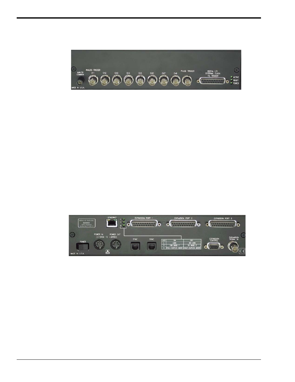
Understanding WaveBook and WBK Connectors
WaveBook/516E Front Panel
The WaveBook/516E Front Panel includes the following connectors and LED indicators.
Analog Common – banana jack receptacle
Channels 1 through 8 – BNC connectors; Channel 1 is also used for Analog Trigger
Pulse Trigger – BNC connector
Digital I/O, External Clock, TTL Trigger – DSUB25 connector
LEDs: ACTIVE – Lights when a sample has been converted by the A/D Converter.
READY – Lights when the WaveBook/516E’s internal Ethernet module establishes communication.
POWER – Lights when power is turned on and is present.
WaveBook/516E Rear Panel
The upper row of the WaveBook/516E rear panel includes a label with a barcode for the device serial
number and a MAC Address (Internet Protocol Address). The row also has an Ethernet Port, three LEDs
(designated L, T, and D), and three Expansion Ports. The panel’s lower row includes a Power Switch,
one DIN5 Power In connector, one DIN5 Power Out connector, two SYNC (synchronization ports), an
LED legend, a 15 pin Expansion Control connector, and a BNC Expansion Signal In connector.
Additional detail follows. Items described below are done so from left to right, when looking at the rear
panel.
MAC Address Label: The Media Access Control (MAC) label is located in the upper left corner of the
rear panel. The label shows the device serial number in barcode and base 10 formats. It also shows the
Ethernet address (MAC Address) which is derived from the serial number in hexadecimal. If prompted to
enter a serial number in software, use the base 10 number. Conversion to a hexadecimal number for use
in addressing will be automatic.
Note: If your network administrator asks you for a MAC number or MAC Address, provide him [or her]
with the hexadecimal number that is located at the bottom of the label.
ETHERNET: The 10/100BaseT Ethernet port can connect to the Ethernet port of the host PC, or to an
Ethernet network. Either of two Ethernet patch cables may be used to make the connection. CA-242 is a
1.5 foot cable. CA-242-7 is a 7-foot cable. Note that the Ethernet connector has two built in LEDs that
indicate traffic flow. These are discussed with the three other Ethernet-related LEDs. Note that the
Ethernet cable length must be <10m in order for the system to be CE Compliant.
2-2 System Setup and Power Options
947191
WaveBook User’s Manual