Cable review – Measurement Computing WaveBook rev.5.3 User Manual
Page 62
Cable Review
CA-35-12 (1 foot) and CA-35-2 (2 foot) DB25 Male to DB25 Female Parallel
Cables. Either of these two cables can be used to connect the parallel port of one
device to that of another. The cables are typically used to connect a WaveBook’s TO
COMPUTER (PARALLEL PORT) to the EPP connector of the host PC.
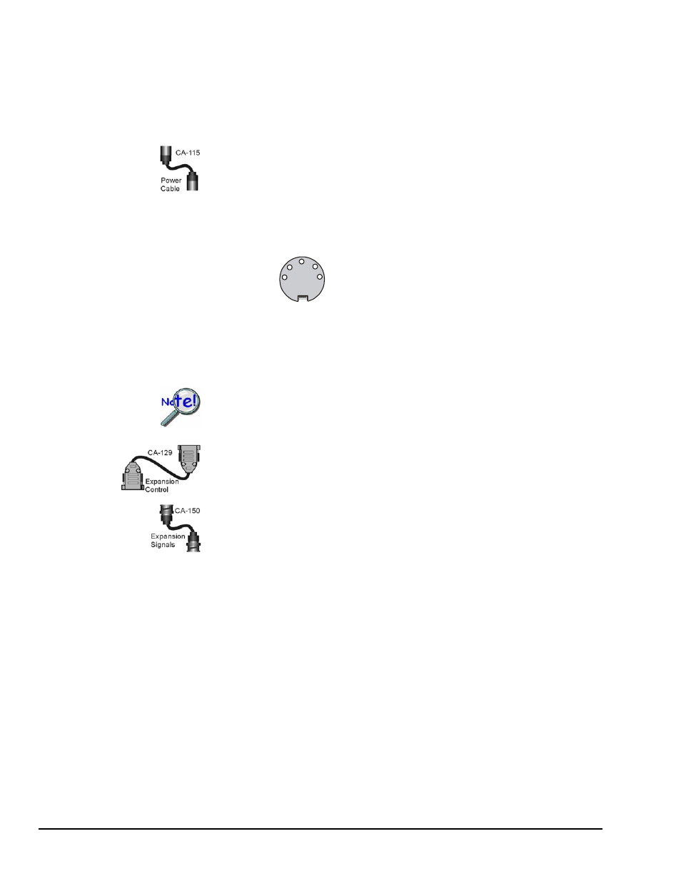
CA-115 Power Cables. CA-115 cables are 6 inches long and have two 5-pin male
DIN connectors. CA-115s are frequently used to link WaveBook’s POWER OUT
connector to a WBK expansion module’s POWER IN connector. CA-115 cables are
also used to link an expansion module’s POWER OUT connector to the next daisy-
chained module’s POWER IN connector.
CA-115 cables and the device DIN5 connectors (see following figure) are limited
to 5 amps at 15 VDC.
3 Retur
+10 to +30 V 4
+10 to +30 V 1
2
Return
5 No conn
DIN 5 Power
Pinout*
Power is supplied to WaveBook modules via a DIN5
type connector located on the rear panel of the
device.
*The DIN5 pinout [to the left] is based on an external
view of a WaveBook rear panel.
Note: An optional CA-116 power cable is available. The CA-116 permits the system to be
plugged into a vehicle cigarette lighter, allowing use of the vehicle’s battery as a
power supply for the WaveBook device.
Calculate system amp load prior to creating a system daisy-chain. Although
WaveBook device connectors and CA-115 and CA-116 power cables have 5 amp
limits, TR-40Us are limited to 2.2 amps. Tables for determining amp load are
provided in the Calculating the System Power Requirement section of Chapter 2.
CA-129 Expansion Control Cables. Control messages are carried by CA-129
expansion-control cables with HD-15, plug and socket connectors. The first expansion
unit’s control input is driven from the main unit’s control output. Control inputs of
additional WBK modules are driven from the preceding unit’s control output.
CA-150 Expansion Signal Cables. Expansion signals are carried by a CA-150-1
male BNC to male BNC coaxial cable. Each WBK module drives a common parallel
analog bus that carries the signals to WaveBook’s Analog-to-Digital Converter
(ADC). Each WBK module has EXPANSION SIGNAL IN and EXPANSION
SIGNAL OUT connectors for daisy-chaining multiple units.
CA-177 Strain Gage Cables. CA-177 is an optional set of eight strain-gage cables
intended for use with the eight channels of WBK16. Discussions of the CA-177
strain-gage cable and bridge applications are contained in the WBK16 document
module.
CA-217 Digital Expansion Cables. These 8-inch cables are used for connecting one
or more WBK17s to a WaveBook/512A, /516, /516A, or /516E. The CA-217 cable
has a DB25M connector for Digital Expansion Out and a HD26M connector for
Digital Expansion In.
CA-242 and CA-242-7 Ethernet Patch Cables. CA-242 is a 1.5 foot cable that can
be used to connect a WaveBook/516E to an Ethernet port on a PC or network. CA-
242-7 is a 7-foot cable that can be used for the same purpose.
CA-74-1 and CA-74-5 SYNC Cables. 1-foot and 5-foot cables, respectively, that are
used to synchronize multiple devices. WaveBook synchronization applies only to “A”
and “E” Series devices.
3-2 System Examples
897895
WaveBook User’s Manual