Ce300 handling considerations – MicroE CE300 ChipEncoder User Manual
Page 6
Page 6
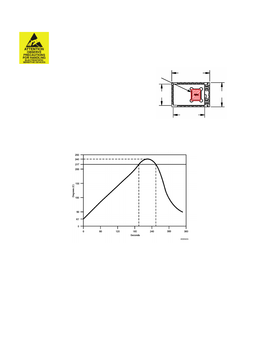
Solder Paste Recommendation and Reflow Profile
ChipEncoder
™
CE300 Handling Considerations
•
Note: ESD precautions should be taken at all times.
Prior to reflow soldering, particular attention must be paid to preventing ESD damage as the damage
threshold is 500V.
Lead-Free Solder Reflow
The CE300 can be soldered to your PC board using industry standard solder reflow techniques. The profile above illustrates a typical temperature profile.
Use a temperature-controlled convection or IR reflow oven and SAC305 solder paste with no-clean flux in either air or an inert atmosphere (N2).
The temperature should be measured on the carrier board close to the CE300 parts and must not exceed 260°C.
CE300’s have soldered devices under the cover. Therefore, the rate of heating and cooling must be controlled so that it does not exceed 5°C
per second to avoid thermal stressing of the devices.
The CE300 inputs and outputs are pre-tinned palladium silver pads with the typical spacing between adjacent input/output pads of 0.2mm (0.008 inches).
The pads are pre-tinned with SAC305 solder alloy. Solder material with good slump characteristics should be chosen to ensure that solder does not bridge or
short during pre-heating in the reflow process.
Hand Soldering
Do not hand solder the ChipEncoder. Hand soldering will cause damage. Castellations are for electrical testing only.
KEEP OUT ZONE
.433[11.00]
.275[6.99]
.36[9.1]
.24[6.1]
• When handling the CE300 do not allow the
pick-up device to touch anywhere in the
“KEEP OUT ZONE”; refer to the illustration
below. Scratches or digs in the KEEP OUT
ZONE can affect the performance of the ChipEncoder.