Reference: grounding and shielding, Installation reference guide – MicroE 1500V Mercury User Manual
Page 15
Page 13
Installation Reference Guide
Mercury encoders require a minimum of 4.75V DC continuously. When designing circuits and extension cables to use Mercury encoders, be sure
to account for voltage loss over distance and tolerances from the nominal supply voltage so that at least 4.75V DC is available to the Mercury
encoder under all operating conditions. The input voltage should not exceed 5.25V DC.
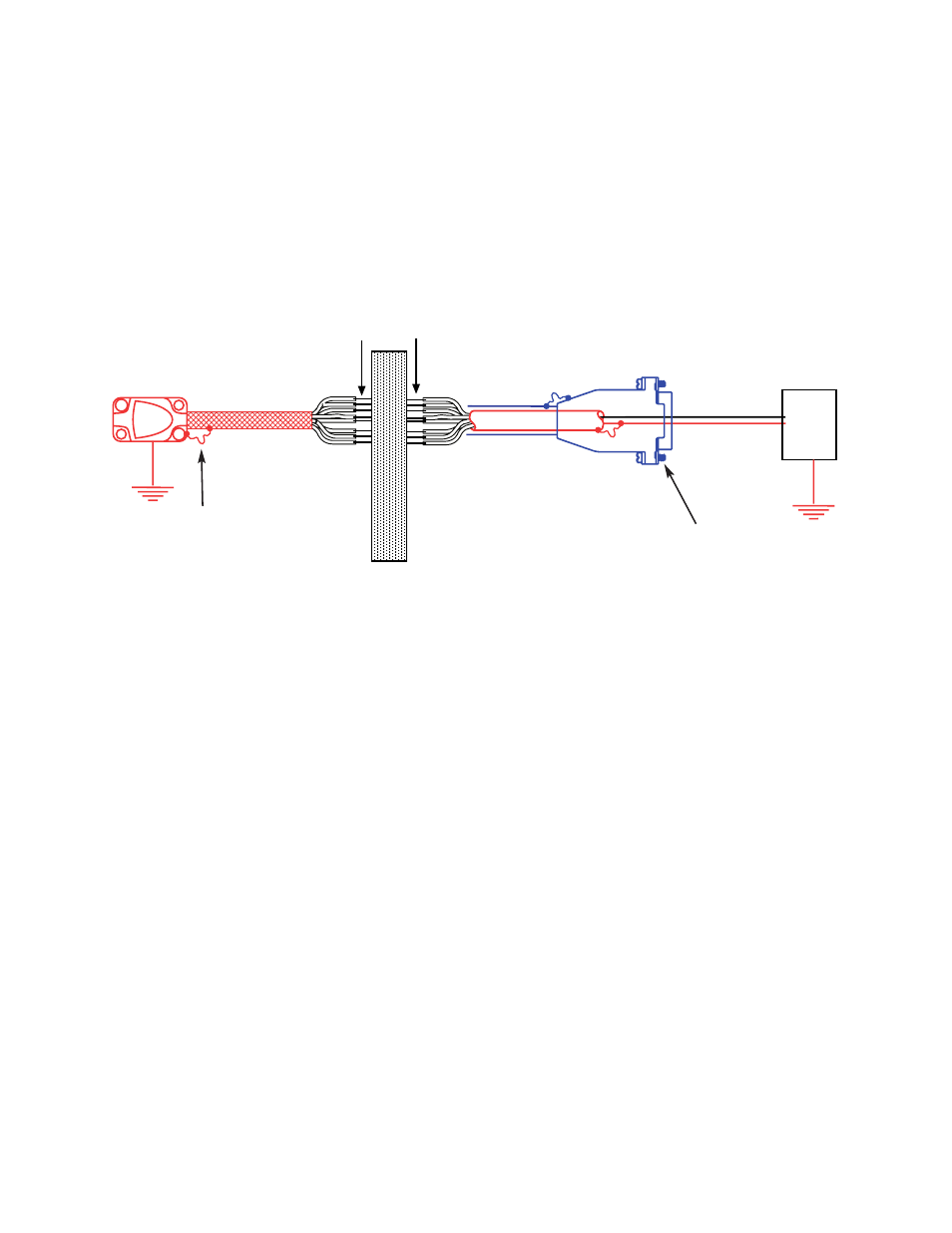
Grounding Instructions for Mercury 1500V Encoder Systems
Recommendations for Power
Vacuum Chamber wall
Note: Specific applications may require a different grounding scheme. Please contact MicroE Systems
Application grouip with details for assistance.
Connector pins
5 Volts
0 Volts
Power
Supply
Electrically conductive mechani-
cal connection (as supplied by
MicroE Systems).
Do not ground shroud.
Shielding Instructions
Customer-installed connectors at the vacuum chamber wall must electrically shield the signal wires from Electro Magnetic Interference,
Radio Frequency Interference and Electro Static Discharge. The connectors' shielding must completely surround the wires with no gaps,
including intimate electrical contact 360 degrees around the outer cable shields at the ends of the cables supplied with flying leads.
The inner shield of the cable that is attached to the SmartPrecision electronics module must be electrically isolated from the outer
shield.
Important Note
MicroE Systems recommends testing the motion subsystem after the Mercury 1500V encoders are installed using your vacuum through-
wall connectors. The testing should prove that the motion system has sufficient immunity to Electro Magnetic Interference, Radio
Frequency Interference and Electro Static Discharge according to the application requirements.
Correct grounding can be implemented in several ways depending on how the customer implements the connections through the vacu-
um chamber wall. The diagram below is suitable where:
•The outer cable shields are electrically isolated from each other at the vacuum chamber wall.
•The sensor is mounted with good electrical contact to a well-grounded surface. (Note that an electrical path through
bearings will not result in a well-grounded sensor.)
Note: specific applications may require a different grounding scheme. Contact MicroE Systems for applications support.