Reference: customer interface cabling, Customer interface cable requirements, Signal wiring – MicroE 1500V Mercury User Manual
Page 16: Shield termination
Page 14
Mercury 1500V
Signal Twisted Pair
A+
Pair 1
A-
B+
Pair 2
B-
Index+
Pair 3
Index-
+5V
Pair 4
GND
Customer Interface Cable Requirements
Customer cables that interface to Mercury series encoders must have the following characteristics:
• Twisted pair signal wiring.
• Characteristic impedance of 100-120 ohms.
• Sufficient wire gauge to meet the minimum voltage requirement at the encoder, for example 24AWG gauge wire for a 2m length cable.
Examples of acceptable cables with 24 AWG gauge wire and 4 twisted pairs are Belden 9831, 8104, and 9844 or other
manufacturer's equivalents.
• Single shield cable with a minimum of 90% coverage. Note that a double shielded cable may be required in high-noise applications.
Signal Wiring:
Each differential signal should be connected to a corresponding twisted pair as follows:
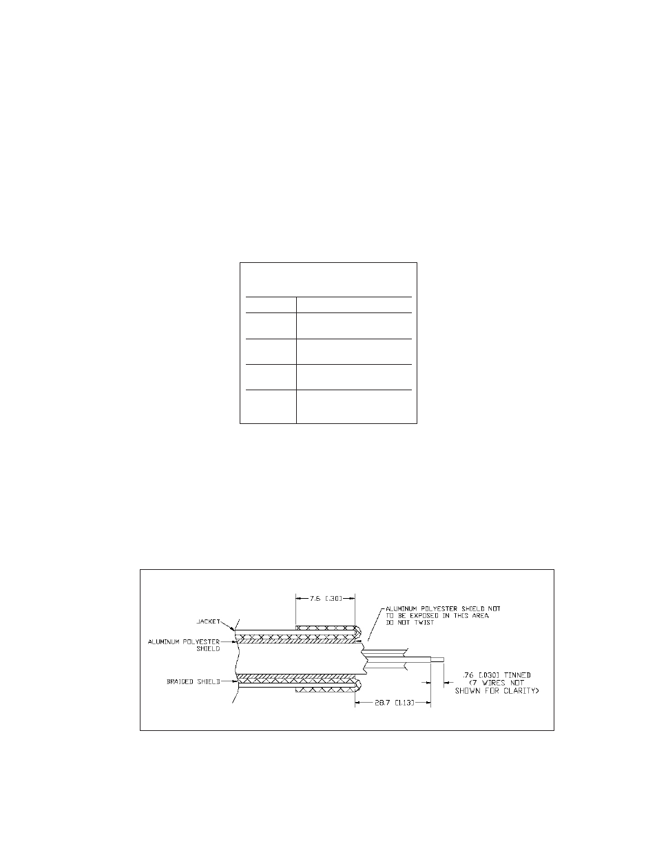
Shield Termination:
The customer's cable shield should be in 360° contact with the connector shroud and the connector shell to provide complete shielding. The
connector shell should be metal with conductive surfaces. Suggested metal connector shells for use with Mercury 3500, 3000, 3000Si,
and 2000 encoders: AMP 748676-1 or equivalent; for Mercury 1000 and 1500V encoders: AMP 745172-3, -2, or -1 where the dash number is
dependent on the customer's outside cable diameter. The shield should be terminated as illustrated in the following diagram.
Fold braided shield back over jacket. Example shows double-shielded cable. Dimensions shown
are for illustration only.