Rotary encoder alignment-using sin/cos signals, Installation instructions – MicroE 1500S Mercury User Manual
Page 13
Page 11
4
INDEX TRACK ALIGNMENT
The M1500S must be aligned for both the main
and index tracks. When properly aligned, the
sensor will produce an index window as the
sensor passes over the index mark. The index
window is approximately one fringe wide
(20µm). To verify proper index track alignment,
use a digital oscilloscope triggered on the index
window. Refer to the interface drawing for the
index window pinout.
Confirm proper alignment of the main track over
the full range of motion. If not aligned over the
entire range of motion, loosen the sensor
mounting screws and repeat steps 4 and 5.
x
Y
Z
θ
z
To align the sensor, move it
in the Y or
θ
z directions.
5
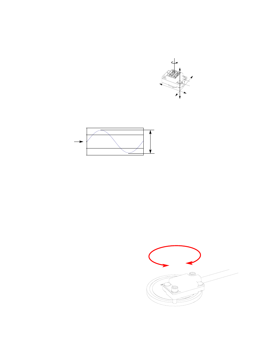
MAIN TRACK ALIGNMENT
If benching dimensions cannot be provided, proper sensor
alignment may require minor adjustments to the sensor
position with respect to the scale. This can be performed by
maximizing the sine signal from the M1500S.
Using an oscilloscope, monitor the sine or cosine signal (refer
to the interface drawing for pinouts) while moving the sensor
over the scale. Align the sensor until 0.8 volts peak-to-peak
+/- 25% is obtained. When alignment is completed, tighten
the sensor mounting screws (0.37Nm [3.3 inch-lbs.] maximum
torque).
Installation Instructions
Rotary Encoders - Using Sin/Cos Signals - Alignment
0.8 Vpp
1.7 V offset
(nominal)