Linear encoder alignment-using alignment tool, Installation instructions, Linear encoders - using alignment tool - alignment – MicroE 1500S Mercury User Manual
Page 7
Page 5
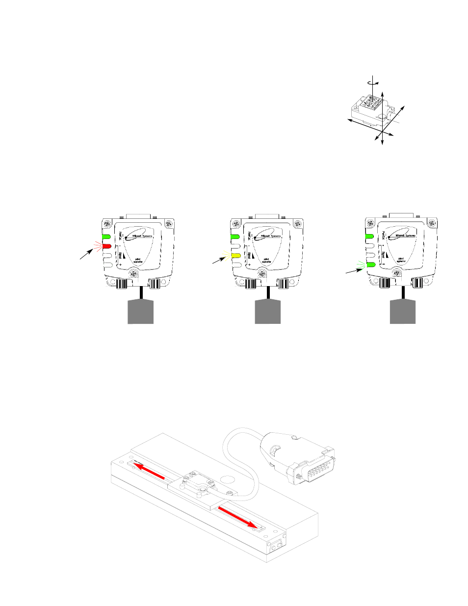
Proper sensor alignment may require minor adjustments to the sensor position with
respect to the scale. This can be performed easily using the optional SmartPrecision
Alignment Tool as illustrated below.
The red, yellow, or green LED will light depending on sensor alignment. Slowly
move the sensor by allowing it to slide on the mounting surface until the green
LED, is illuminated. Optimal alignment will be displayed as a “Bright Green” LED.
IMPORTANT:
Confirm that the green LED blinks when passing over the index.
If not, readjust the sensor in the Y direction and repeat the above procedure.
When alignment is completed, tighten the sensor mounting screws
(0.37Nm [3.3 inch-lbs.] maximum torque).
6
5
Confirm green over the full range of motion by sliding
the scale past the sensor. The “green” LED must
remain on over the entire range. If not aligned over the
entire range of motion, loosen the sensor mounting
screws and repeat step 5.
x
Y
Z
θ
z
To align the sensor, move
it in the Y or
θ
z direc-
tions.
SmartPrecision
Alignment Tool
Improper
Alignment LED
Red
Power/
Calibration
Power/
Calibration
Power/
Calibration
Improved
Alignment LED
Yellow
Proper
Alignment LED
Green
Optimal
Alignment LED
Bright Green
15 pin D
connector
to sensor
15 pin D
connector
to sensor
15 pin D
connector
to sensor
SmartPrecision
Alignment Tool
SSAT1500S
SmartPrecision
Alignment Tool
SSAT1500S
SmartPrecision
Alignment Tool
SSAT1500S
Installation Instructions
Linear Encoders - Using Alignment Tool - Alignment