Section 2 installation instructions, 1 location, 2 auxiliary power requirements – MK Products Pulse+ User Manual
Page 10: 3 weld cable connections
Pulse+ Owner's Manual Page 10
Section 2
INSTALLATION INSTRUCTIONS
2.1 LOCATION
The Pulse+ should be located to provide adequate ventilation for cooling. There
should be a minimum of four inches on each side.
CAUTION: Overheating of unit can cause possible damage
to internal components.
There should be access to both the front and rear of the unit to allow quick
disconnection of welding cables for applications not requiring pulse capabili-
ties. For standard welding, the connectors can be locked together, thus
removing the Pulse+ from the circuit.
CAUTION: DO NOT operate the Pulse+ in the OFF position.
Doing so will cause damage to internal parts.
2.2 AUXILIARY POWER REQUIREMENTS
The Pulse+ is designed to operate on 220 volt 1 Ampere 50-60 Hz circuit. This
circuit could be a wall outlet or from an outlet on the power supply, if one is
provided.
2.3 WELD CABLE CONNECTIONS
Provided with the Pulse+ are two Dinse 400 Amp male weld cable connectors
(P/N 153-0755) and two Dinse 400 Amp female weld cable connectors (P/N
153-0813).
Select adequate size welding cable for the anticipated maximum weld current.
Keep the cables as short as possible and as close together as possible.
Excessive cable length adds resistance which may reduce the output.
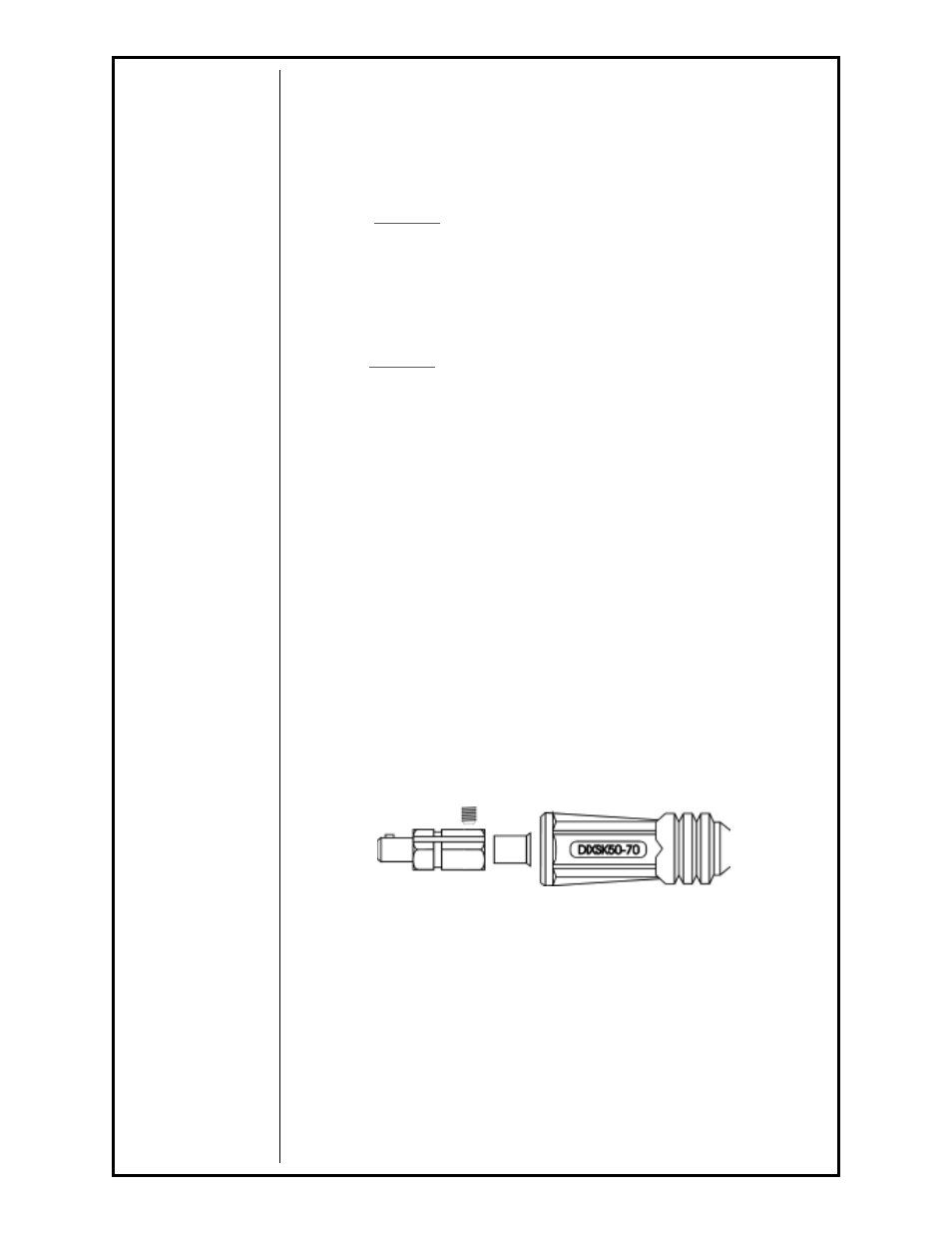
To install the connectors, use Fig. 1 for proper part orientation.
NOTE: Place the connector boot over the cable before cutting back the insulation.
This will keep the copper strands from becoming frayed.
CONNECTOR PART ORIENTATION - Fig. 1