Section 4 operation, 1 power switch, 2 voltmeter – MK Products Pulse+ User Manual
Page 12: 3 pulse operation
Pulse+ Owner's Manual Page 12
Section 4
OPERATION
CAUTION: DO NOT ATTEMPT TO WELD WITH THE PULSE+ TURNED OFF
For non-pulsed operation, the connectors can be locked together, thus removing
the Pulse+ from the circuit.
4.1 POWER SWITCH
Placing the power switch in the On position energizes the fan and control
circuitry. The red indicator lamp should be on at this time.
CAUTION: If the fan does not operate when the power switch is in the On position,
DO NOT attempt to weld. Without proper air flow, unit can overheat and cause
damage to internal parts.
4.2 VOLTMETER
The voltmeter on the front of the Pulse+ will read average voltage during
welding. Average amperage can be read off of the power supply amp meter.
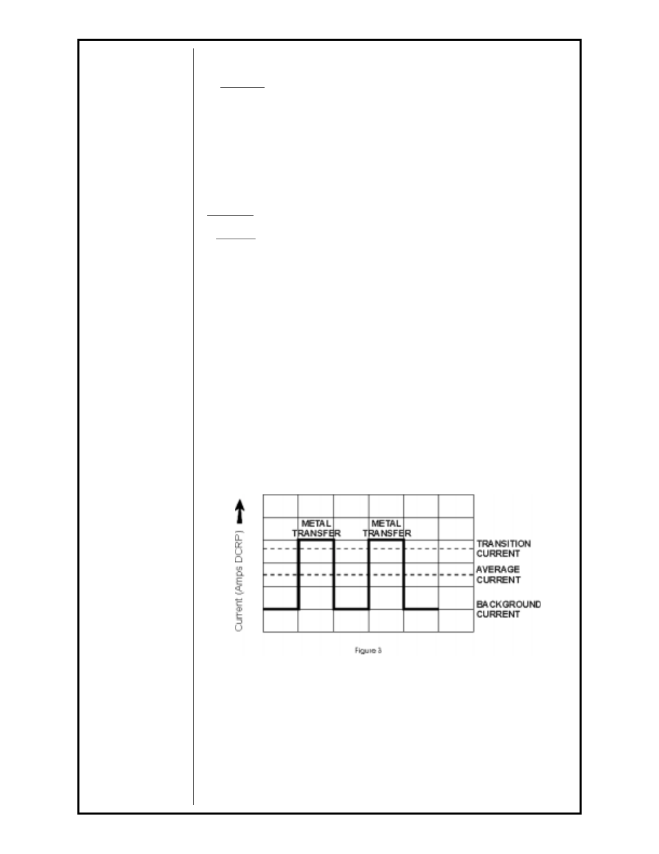
4.3 PULSE OPERATION
In pulsed spray welding, the current is varied from the background level to a
peak level. The background level is well below the transition current, while the
peak level is well into the spray arc region, Figure 3. During the peak level,
one droplet is transferred to the work. The current then drops to the back-
ground level, which allows the puddle to cool, at which time no metal is
transferred.