Mogar Music PMS User Manual
Page 11
10 - PMS
USER’S MANUAL
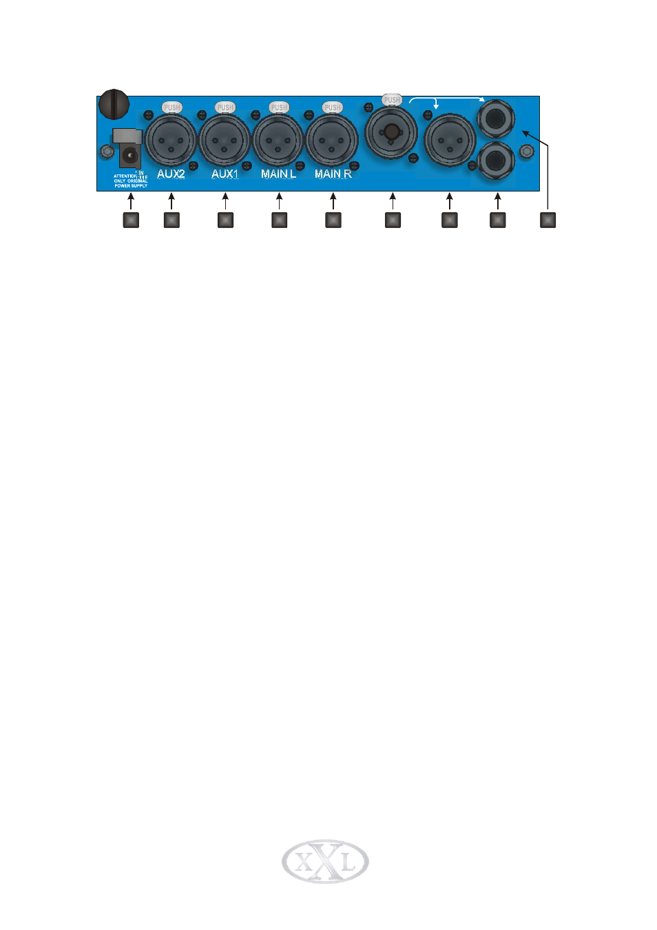
Fig. 4.2 Back panel connections
1) Power Supply connector.
2) AUX2 balanced input connector; it is possible to lift the ground of this input via the
top cover of the PMS moving the dedicated jumper inside the unit.
3) AUX1 balanced input connector; it is possible to lift the ground of this input via the
top cover of the PMS moving the dedicated jumper inside the unit.
4) MAIN LEFT balanced input connector; it is possible to lift the ground of this input via
the top cover of the PMS moving the dedicated jumper inside the unit.
5) MAIN RIGHT balanced input connector; it is possible to lift the ground of this input
via the top cover of the PMS moving the dedicated jumper inside the unit.
6) DIRECT INPUT balanced input connector; it is possible to lift the ground and to
reverse the phase of this input via the top cover of the PMS moving the dedicated
jumpers inside the unit. If you use the jack input of this connector an auto pad
function of 20dB will be inserted.
7) DIRECT INPUT balanced parallel output connector; CH1 RIGHT AUX INPUT. Use
as auxiliary right audio input for CH1, connect balanced or unbalanced standard
phone jack.
8) AUX3 balanced input connector.
9) DIRECT INPUT parallel output of the jack input.
POWER IN
DESIGNED AND MADE IN ITALY
BALANCED
INPUT
BALANCED
INPUT
BALANCED
INPUT
BALANCED
INPUT
BALANCED
PARALLEL OUT
BALANCED
INPUT
PARALLEL
OUTPUT
+4dBu
+4dBu
+4dBu
+4dBu
AUX2
AUX1
MAIN L
MAIN R
DIRECT
DIRECT
BALANCED
INPUT
AUX3
1
2
3
4
5
6
7
8
9