Montigo E36DV-TV User Manual
Page 3
0 9 / 9 6
Page 3 of 14
E36DV-TV
INSTALLATION OF DIRECT VENT
A complete Econo Plus 36DV-TV vent system may comprise of
six individual components: (see figure 5. page 4)
A - Termination
MTK-5 (5" length)
MTK-9 (9" length)
B - Stucco Kits
MSR (stucco frame)
MOSR (stucco can)
C - Solid section & elbow
MIHR-6 (6 ft. length)
MIHR-10 (10 ft. length)
D - Flex sections
MFL-1 (1' 6" section)
MFL-2 (2' 6" section)
MFL-3 (3' 6" section)
MFL-4 (4' 6" section)
E - Solid sections
MEXT-1 (1' 6" section)
MEXT-2 (2' 6" section)
MEXT-3 (3' 6" section)
MEXT-4 (4' 6" section)
F - 90 degree elbow
MEL90 (90 deg. elbow)
Example: For our shortest venting configuration use compo-
nents A, B, and F. (see Figure 5).
Example: A 10' section and elbow (MIHR-10) used in
conjunction with 3 ft. flex section (MFL-3) will, when extended
in a five foot chase, allow for a maximum horizontal run of
twelve and one-half feet from the centre of the fireplace to
outside wall and a minimum of 7'6" when retracted in opposite
direction (see Figure 6 and 7).
"D" flex sections and "E" solid sections may be used in
conjunction with one another to obtain different possible
horizontal length installations. NOTE: Flex section must not
exceed maximum horizontal length of 3 feet. (see Figure 7.1)
Note: DO NOT STRETCH flexible connector to gain
extra length. These connectors are Flexible only to
allow for directional changes, which must not exceed 90
degrees.
A minimum height of 43" to centre of horizontal flue is
required.
All vent pipes must maintain a minimum of 1"
clearance to combustible materials.
Note: It is imperative for satisfactory operation of the
Econo Plus 36DV-TV fireplace that no venting compo-
nent be modified in any way. All components have been
manufactured to eliminate the need for modification
when properly selected and installed.
CAUTIONS AND REQUIREMENTS
DIRECT VENT TERMINATION LOCATION
This section is used to determine where your direct
vent termination will be located.
VENT TERMINATIONS SHALL NOT BE RECESSED IN
WALLS OR SIDING.
CAUTION
1).
Extremely important: In heavy snow areas take extra
care to prevent against blocking vent termination with
snow removal equipment.
2). Flue gases exiting vent terminals are very hot and must
not be restricted to assure fireplace combustion is not
affected.
3). Do not place, build any obstruction, plant any bushes
or for any reason attempt to conceal the vent
termination. To do so will affect the operation of
the fireplace and may be hazardous.
4). National Standards require that vent terminations be
protected with an additional screen on patio's, decks and
any areas accessible to public. For maximum safety we
recommend all terminals below 7' from grade level be
installed with a certified Econo Plus protective screen. (MTKG)
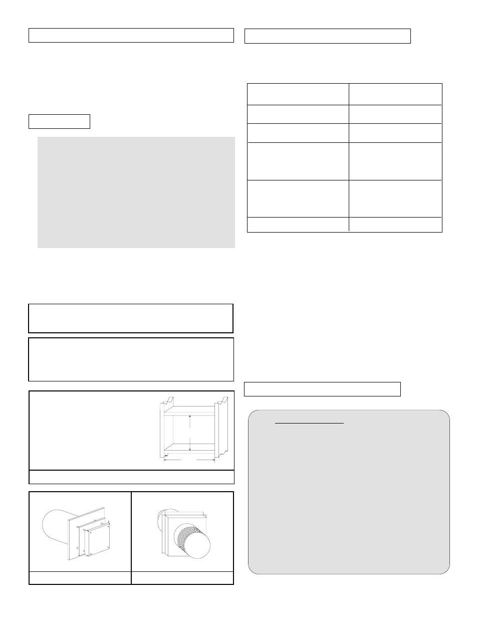
FIGURE 4. VENT TERMINATION FRAMING.
MTK-5 or MTK-9
MTKO-5 or MTKO-9
*
IMPORTANT:
When using MTK or MTKO with
MOSR: Framed opening must be 12"
X 12"
When using MTK or MTKO:
Framed opening must be 11" X 11"
*
12
12
*
FOR DETAILED SKETCH OF ALLOWED
TERMINATION LOCATIONS SEE APPENDIX A
FOR VINYL SIDING APPLICATIONS ALL MTK
TERMINATIONS MUST BE INSTALLED WITH A
HEAT SHIELD (MTKG) TO PROTECT THE SIDING
FROM ANY HEAT DAMAGE. MTKO TERMINATIONS
DO NOT REQUIRE A HEAT SHIELD.