Montigo E36DV-TV User Manual
Page 8
0 9 / 9 6
Page 8 of 14
E36DV-TV
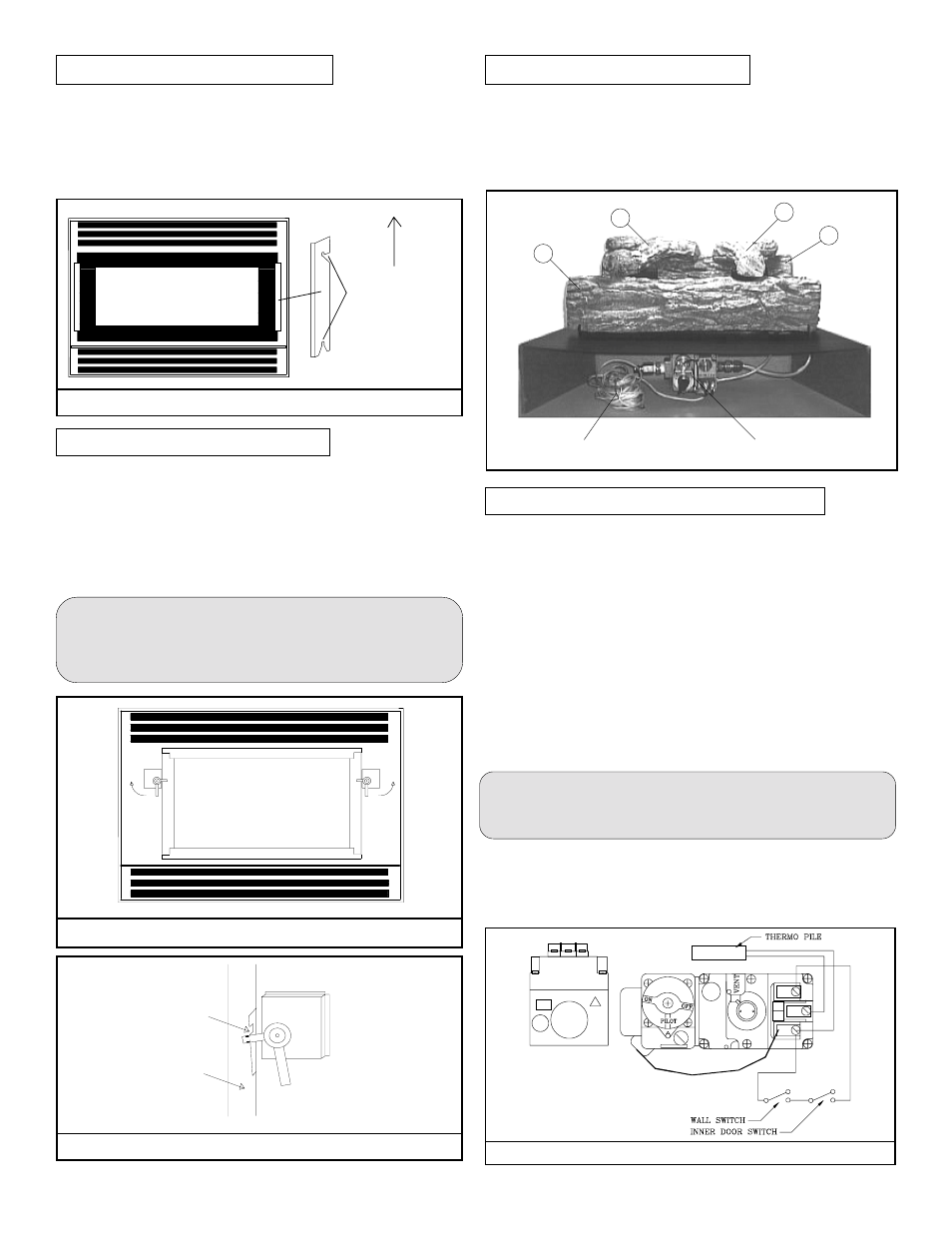
REMOVAL OF OUTER DOOR
Lift panel upwards
and outwards until
panel releases from
mounting pins.
FIGURE 13. SAFETY LOCK
Easily removed for cleaning and servicing. Although this pane is
made of a very tough tempered glass, always handle it carefully and
place in a safe location where it will not be broken or damaged.
To remove the outer glass panel lift upwards and outwards. This will
release the panel from the mounting pins. See Figure 11.
REMOVAL OF INNER DOOR
To remove inner glass door, outer glass door must first be removed.
Next turn the safety door locks outwards as illustrated in Figure 12.
Note: When turning and unlocking the safety door locks a small
additional pressure is required to start the unlocking procedure.
This is because a latch pin of the safety door lock is seated into a latch
plate notch (see Figure 13). This ensures the safety door lock is in
its correct position, maintaining the door seal is under constant
spring pressure.
IMPORTANT: For your safety when replacing in-
ner door to its original position always assure the
safety door latch pin is correctly positioned with the
notch in the latch plate. (see Figure 13).
Turn
Turn
FIGURE 12. INNER GLASS DOOR
Knotch
Door
FIGURE 11. OUTER GLASS DOOR
The EC-Plus 36DV-TV is supplied with four(4) very attractive
cultured oak logs. To install simply place log "A's" rectangular
shaped extension into the log mounting slot located on rear wall
of the burner assembly. Place log "B" onto front log slots.
Place log "C" and log "D" onto pins on the burner bar as shown
below.
A
D
C
B
Wire to
wall switch
Control Valve
LIGHTING PILOT AND MAIN BURNER
To light pilot it is necessary that you remove outer and inner glass
door (refer to sections on glass door removal). The gas control valve
is located behind the brass trim in the centre of the fireplace (see
Figure 14 below). Before lighting the pilot, make sure that the gas
line is connected and the gas shut-off valve is turned to the ON
position. To light the pilot we recommend the use of a long match
or removal of log“D”:
a) Partially depress and turn dial on gas control valve to “OFF”
position and wait 5 minutes.
b) Turn dial to pilot position, depress dial and light pilot burner,
hold for1 minute, then release. If pilot does not remain
ignited, repeat, allowing a longer time to elapse before
releasing dial.
c) Re-install inner and outer glass door.
NOTE: For your protection and safety, main gas burner can not
be activated until inner glass door has been re-installed to activate
a safety cut off switch.
d) To light the main burner, turn dial to “ON”, then turn on
remote switch.
e) Turn off flame with remote switch. For complete shut down,
slightly depress gas control valve dial and turn to “OFF”
position.
FIGURE 14. ROBERT SHAW GAS CONTROL VALVE
FOR ALTERNATE
GAS VALVE SEE
FIGURE 16 ON THE
NEXT PAGE.
INSTALLING LOG SET