Montigo E36DV-TV User Manual
Page 6
0 9 / 9 6
Page 6 of 14
E36DV-TV
INSTALLING THE REMOTE SWITCH
The Econo Plus 36DV-TV is equipped with a remote-operated
valve, located behind the removable brass grille, to the right of the
gas control valve (refer to figure 14.) The valve is pre-wired and
completely self contained to generate its own power DO NOT
connect any external power to it. Note: The switch location must
not exceed 30' from fireplace.
GENERAL VENT/PIPE INFORMATION
1.) All joints must be secured with the minimum of two screws
per joint.
2.) Horizontal runs must be supported by a minimum of two
supports per horizontal run. A minimum of one screw on
each side of support is also required.
3.) Both ends of the vertical sections are slip sections and are
made to slide over fireplace outlets and horizontal section
inlets.
A
B
C
Horizontal
Vertical
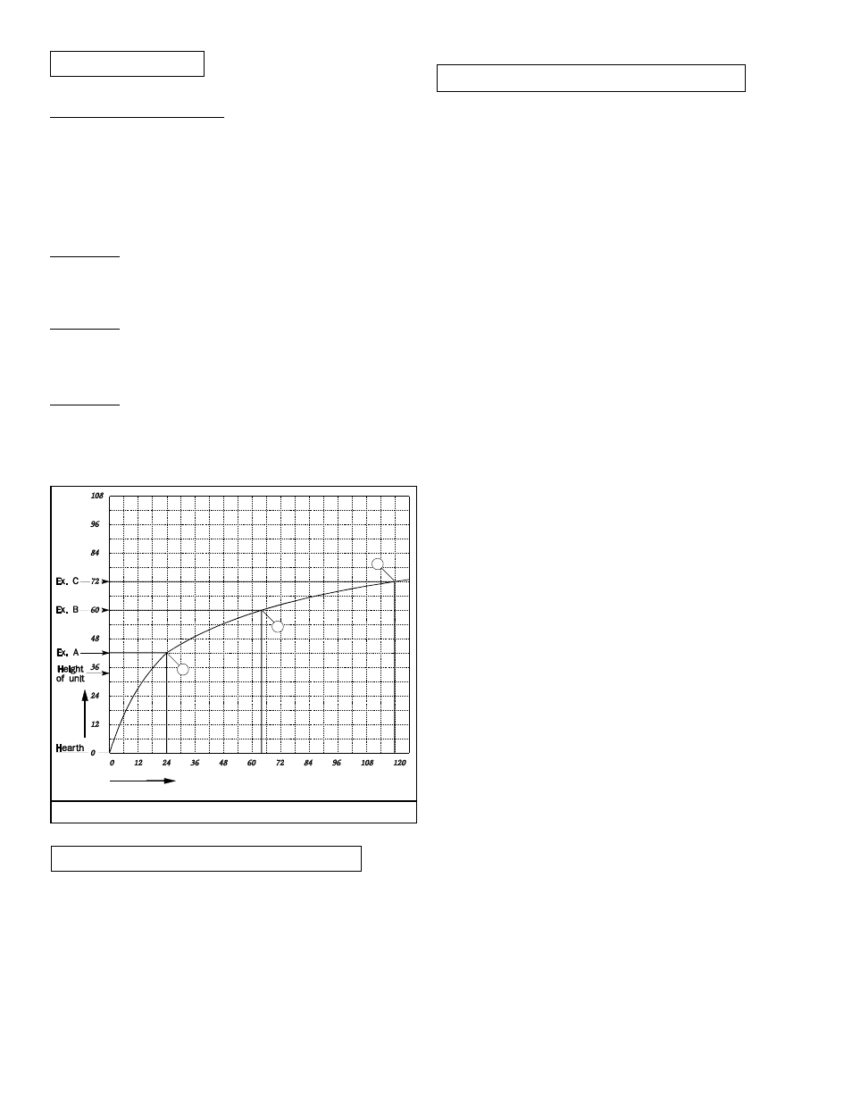
VENTING GRAPH
VENTING GRAPH
Venting graph is used for top vent direct vent model only.
How to use the venting graph:
1 Determine the height for the centre of the 7" vent
elbow and mark a horizontal line until it intersects
with the slanted graph line.
2. From the point of this intersection draw a vertical line
to the bottom line of the graph.
3. Select the indicated dimension and position the
fireplace in accordance with the same.
Example A:
If the vertical dimension from the floor of the fireplace
is 42" the horizontal run to the wall flange of the vent
termination must not exceed 24".
Example B:
If the vertical dimension from the floor of the fireplace
is 60" the horizontal run to the wall flange of the vent
termination must not exceed 64".
Example C:
If the vertical dimension from the floor of the fireplace
is 72" the horizontal run to the wall flange of the vent
termination must not exceed 120". (Maximum
allowable horizontal length).