Obvius A89DC-08 User Manual
Page 7
If you are using software or a PLC to communicate with the A89DC-08, write the address value to Modbus register 41010.
The address must be between 1 and 247.
If you are using an AcquiSuite Data Acquisition Server, use your web browser to view the AcquiSuite configuration
webpage. Locate the A89DC-08 in the Modbus Device List. Click on the device in the list to view the details for the
A89DC-08. Next, click the configure button at the bottom of the page, and then the “Advanced” button at the bottom of the
configuration page.
The Advanced configuration button will display a number of parameters for the A89DC-08. One option is the Modbus
address. Set the required Modbus address (1-247) and click the save button at the bottom of the page.
Return to the Modbus device list page. It may take several minutes for the AcquiSuite to locate the new address for the
device and for the A89DC-08 to appear on the list again. Once it does, click the device and configure a logical name to
identify the device in the list.
Step 7 - Once the A89DC-08 is powered up and communications have been confirmed, the DC load wires should be
installed. Remove power from the A89DC-08 before installing the load wires.
WARNING: Disconnect power and lock-out all power sources during installation.
DO NOT CONNECT VOLTAGE OR CURRENT INPUTS LIVE
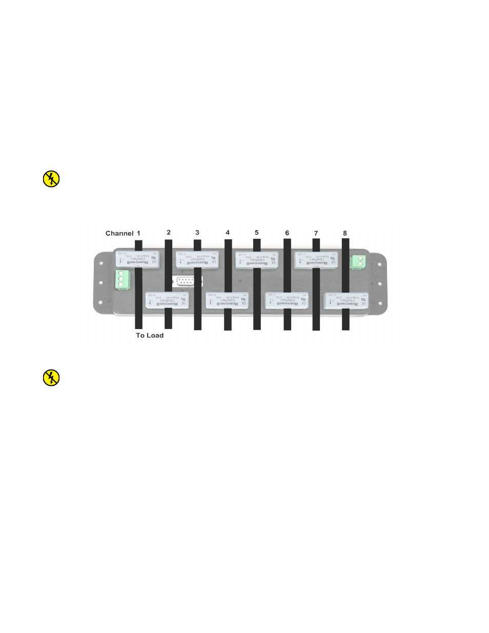
Each DC load wire should be run through the opening in the A89DC-08 hall effect sensor. The arrow on the top of the
sensor indicates the direction of current flow, and should point in the direction of the load. In a solar PV system, the arrow
should point towards the inverter.
This illustration shows the 8 load wires passing through the individual hall effect sensors. The channel number for each load
wire is shown at the top.
WARNING: The DC load wire that passes through the hall effect sensor opening must be insulated, and of sufficient
thickness to prevent the wire from getting warm due to current flow. Refer to local electrical codes for specific wire
size requirements. The DC Load Wire must not make any electrical connection to the A89DC-08. It should only pass
through the hall effect sensor opening.
When installing the load wire, do not pull on, or otherwise stress the hall effect sensors.
Step 8: power up the A89DC-08 and the load wires and confirm the readings match the expected current flow.
Note: If cleaning is required, use a dry towel to remove dust from the A89DC-08. Do not use fluids to clean the A89DC-08.
Page 7
A89DC-08 – DC Current Monitor