Olson Technology LP-CH-16B User Manual
Page 5
025-370403 REV X9
Page 5 of 11
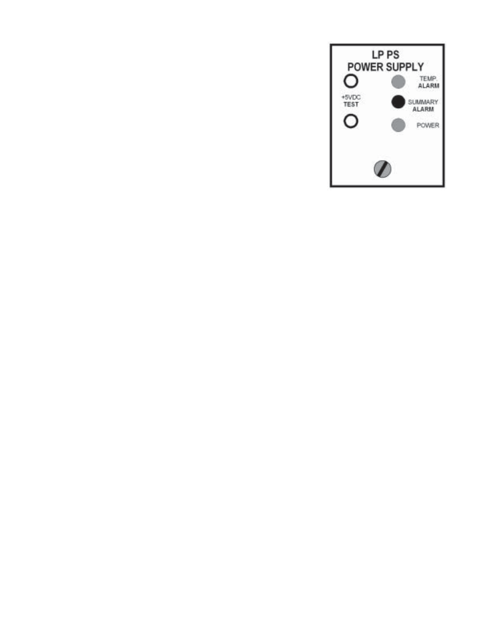
There are 3 LED’s on the front of the power supply.
The temperature alarm LED is normally green. It changes to red if any
fan is open, missing, or frozen. It also goes red if the unit’s internal temperature
is too high. This LED is normally on for several seconds after power on
while the fans start up.
The red summary alarm LED is normally off. It lights on any module
alarm or on a temperature alarm.
The power LED is normally green. If the power supply voltage is too
high or too low, it will be red. This will also cause a temperature alarm.
The test points can be used to monitor the bus voltage.
POWER SUPPLIES
A single power supply mounts in the rightmost slot as viewed from the front. Dual supplies mount in the two
rightmost slots. Changing from single to dual supplies does not require any chassis rewiring.
The AC supply automatically accepts 90-132VAC and 180-264VAC at 47-63Hz. The maximum input
power is about 140 watts. The voltage supplied to the modules is approximately 5.25VDC.
The AC input is through an IEC connector on the rear of the power supply. The voltage selection jumper is
not used; the unit will operate with the jumper in any position. If redundant supplies are used, we recommend
plugging them into independently protected power strips.
The Laser Plus system also has a 48V DC input power supply for central office use. See the LP-PS-48V
instruction manual, OT p/n 025-370451, for complete specifications.
OPTICAL TRANSMITTER MODULE
FUSE
The module has an internal miniature 3A SB fuse in a holder. The Littelfuse part number is 0454003. The
Olson Technology P/N is 286-000009.
RF INPUT
The LP-OT-6 laser transmitter accepts a 77 channel flat RF input from +18dBmV to +22dBmV per
channel (50-550 MHz). Digital signals can be added from 550MHz to 870MHz. The power in any 6MHz
bandwidth should be at least 6dB below the picture carriers.
The LP-OT-8 to LP-OT-15 laser transmitter accepts a 77 channel flat RF input from +19dBmV to
+23dBmv per channel (50-550 MHz). Digital signals can be added from 550MHz to 870MHz. The power in any
6MHz bandwidth should be at least 6dB below the picture carriers.
The front panel RF test point has been calibrated at 547.25MHz to read +10dBmV for optimum optical
modulation with 83 channel loading. This level will change with channel loading.
With these frequency ranges, it is extremely important to account for coax cable loss and slope when
making measurements and distributing signals.