Olson Technology LP-CH-16B User Manual
Page 9
025-370403 REV X9
Page 9 of 11
OPTICAL RECEIVER MODULE
DESCRIPTION
The LP-OR is a triple return band receiver in a single module. The receivers have an extended bandwidth
of 200 MHz to allow the use of spectrum multiplication. Individual receivers in the module can be disabled if three
inputs are not available.
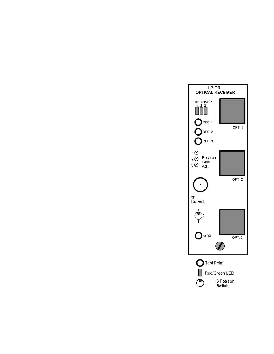
FRONT PANEL
The 3 rectangular red/green status LED’s monitor the receivers’ optical
inputs. They are normally green and change to red on a low or missing optical
input. Any red LED causes a module alarm and a chassis summary alarm.
The 3 DC test points monitor the receivers’ optical inputs. 1mW
(0dBm) is 1V at the test point. Only high impedance meters should be used.
Use the ground test point at the bottom of the module, not chassis ground.
The 3 multi-turn potentiometers set the receivers’ gains. Setting any
gain control fully counter-clockwise will disable that receiver. The LED for a
disabled receiver will always be green. A disabled receiver will never generate
an alarm.
The –20dB RF test point monitors the RF output of any single receiver.
It does not require termination.
The 3 position toggle switch selects which receiver’s output appears at
the test point. Insure that this switch is in the correct position before using the
test point to set the RF gain.
The ground test point should be used when checking optical input
levels.
The SC/APC optical input connectors are on the right of the front
panel, with optional FC/APC connectors available.