Input drive vs. channel loading – Olson Technology LP-CH-16B User Manual
Page 6
025-370403 REV X9
Page 6 of 11
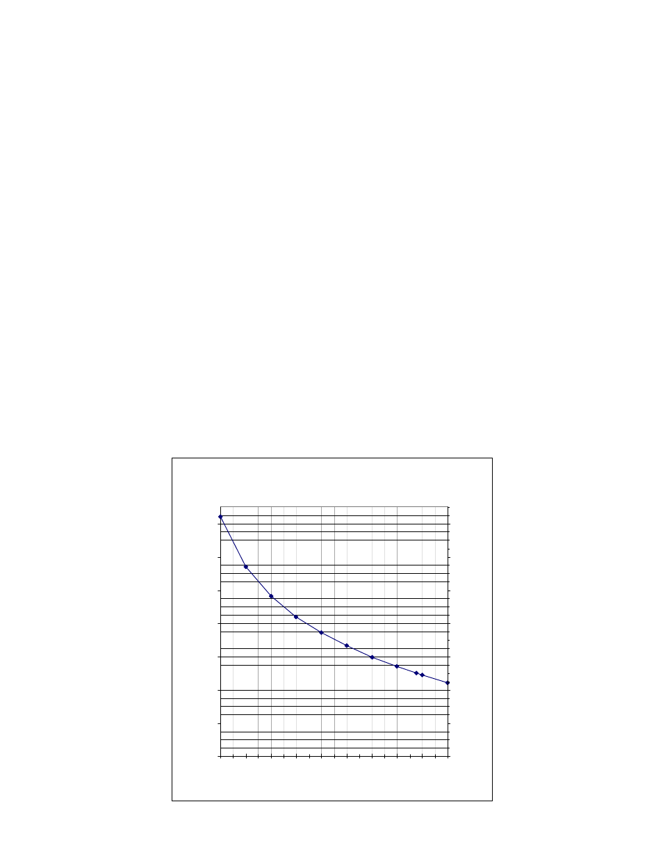
INPUT DRIVE vs. CHANNEL LOADING
The laser RF drive level is the primary determining factor of link distortion and S/N performance. The basic
limitation on input drive is total input power. The following chart shows the approximate input levels versus channel
loading. The left axis shows the nominal RF input level. The unit will work with levels within +/- 2dB of this value.
The right axis shows the test point reading for optimum modulation.
Many systems run their digital channels at 6dB below the analog channels. This is a very convenient level
for calculating loading. At 6dB down, merely divide the number of digital channels by 4 and add to the analog
channels to get the total loading.
The factory test input is 77 analog channels with 42 digital channels at 6dB down. This is 77 + 42/4, which
equals 87.5. This is the 87.5 ch / +20dBmV input point on the graph.
Some systems use an OMI meter to set laser modulation. The LP-OT-6 to LP-OT-15 have been
individually adjusted for optimum performance. Setting all units for the same OMI, instead of using the test point,
will result in reduced transmitter performance.
OPTICAL OUTPUT
The cooled DFB laser outputs 4mW (+6dBm) minimum at 1310 nm. Laser performance has been
optimized for this power level; there is no external adjustment for laser output power.
UNIT
OPTICAL OUTPUT
LP-OT-6
4.00mW
6dBm
LP-OT-9
7.94mW
9dBm
LP-OT-8
6.30mW
8dBm
LP-OT-10
10.0mW
10dBm
LP-OT-12
15.70mW
12dBm
LP-OT-14
25.00mW
14dBm
LP-OT-15
31.60mW
15dBm
Input Level versus Loading
15.0
17.0
19.0
21.0
23.0
25.0
27.0
29.0
10
20
30
40
50
60
70
80
90
100
# of Channels
N
o
m
ina
l I
nput
L
evel
d
B
m
V
5
7
9
11
13
15
17
19
Se
t T
.P.
d
B
m
V