Front panel, Rear panel – Olson Technology LP-OR-304 User Manual
Page 3
LPOR-304 Operating Instructions
Revision A
4 June 2006
PAGE 3 of
10
DESCRIPTION
The LP-OR-304 has dual, redundant return band receivers in a single module. The receivers have an
extended bandwidth of 300 MHz to allow the use of spectrum multiplication. Individual receivers
in the
module can be disabled.
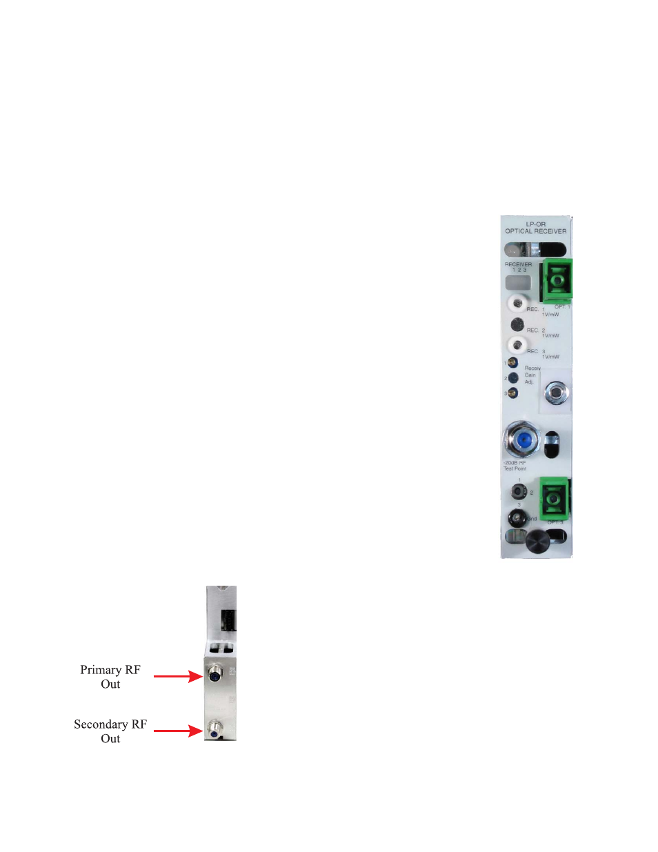
Front Panel
The two rectangular red/green status LEDs monitor the receivers’ optical
inputs. They are normally green and change to red on a low or missing optical
input. Any red LED causes a module alarm and a chassis summary alarm. The
two DC test points monitor the receivers’ optical inputs. One (1) mW (0 dBm)
is 1 V at the test point. Only high impedance meters should be used. Use the
ground test point at the bottom of the module, not chassis ground.
The two multi-turn potentiometers set the receivers’ gains. Setting any gain
control fully counter-clockwise will disable that receiver. A disabled receiver
will never generate an alarm.
The -20dB RF test point monitors the RF output of any single receiver. It
does not require termination.
The two position toggle switch selects which receiver’s output appears at
the test point. Ensure that this switch is in the correct position before using the
test point to set the RF gain.
The ground test point should be used when checking optical input levels.
The SC/APC optical input connectors are on the right of the front panel,
with optional FC/APC connectors available.
Rear Panel
The RF output connectors are on the rear of the unit. Receiver #1 is on the
top. Receiver #2 is on the bottom.
Figure 1 – LPOR-304
Front Panel
Figure 2 – LPOR-304 Rear Panel