Lpor-304 operation overview, Installation, Switch number function off on – Olson Technology LP-OR-304 User Manual
Page 6
LPOR-304 Operating Instructions
Revision A
PAGE 6 of
10
4 June 2006
LPOR-304 OPERATION OVERVIEW
The LPOR-304 redundant receiver consists of two receiver boards, a switch board, and a status/
control board. The upper three LEDs are tri-color ones. The redundancy mode LED is visible through a
vent hole next to the Rx status LEDs. The unit can function as a redundant receiver or as dual
independent receivers.
A single pushbutton switch and an 8-position DIP switch control the major functions. See Figure 4,
page 4 for the switch location. The receiver gain controls will disable their receiver if fully turned CCW.
The status board has a microprocessor and two ADCs to monitor the optical input levels. The
microprocessor stores different responsivities for 1310 nm operation and 1550 nm operation. The voltage
read will be proportional to the optical power in mW. The microprocessor performs a 10*LOG
10
function
to convert the mW value to dBm. All alarms and transfer decisions are based upon dBm levels. An 8-
position DIP switch, which is accessed by removing the left cover, sets all configurable parameters. All
alarm and display logic would be handled by the microprocessor. The user can select one of eight optical
switching thresholds via the DIP switch.
The microprocessor switches from the PRIMARY to the SECONDARY receiver in 50 ms or less
when the primary receiver indicates that it has insufficient light. The microprocessor also drives two
analog test points on the front panel via PWM outputs.
In the redundant mode, Rx1 is the PRIMARY receiver and Rx2 is the SECONDARY or BACKUP
receiver. In order to swap the fiber priority, the user must swap the input fibers.
INSTALLATION
The user must first set the DIP switches (SW1 on the 714 board) for the specific application (see
Figure 4, page 4 for location). The default factory shipping position for all switches is OFF. These
switches are read at least twice per second and updated when changes are sensed. The eight switches
function as follows:
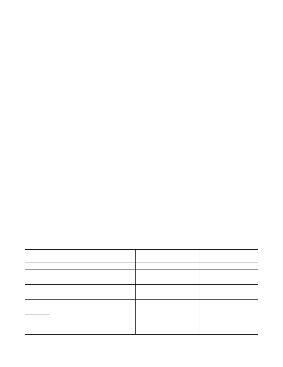
Table 2 – DIP Switch Settings
Switch
Number
FUNCTION
OFF
ON
1
Unit Mode
Redundant
Independent
2
Primary Input Wavelength
1310 nm
1550 nm
3
Secondary Input Wavelength
1310 nm
1550 nm
4
Optical Level Hysteresis
Loose (3dB)
Tight (1dB)
5
Restore Delay
Instantaneous
Delayed (60 Seconds)
6
Sets the Optical Switching Threshold in
the High to Low Direction
000 = -19 dBm
001 = -17 dBm
010 = -15 dBm
011 = -13 dBm
100 = -10 dBm
101 = -7 dBm
110 = -4 dBm
111 = -1 dBm
7
8