Digital room sensor, Mounting and wiring – Orion System Digital Room v.1 User Manual
Page 5
Operator Interface
DIGITAL ROOM SENSOR
5
Mounting
CAUTION: Do not touch the front face of the sensor while you
are plugging in the modular sensor cable. Touching the front face
of the sensor while plugging in the cable may prevent proper initial-
ization and keep the buttons on the sensor from working properly.
The Digital Room Sensor is designed to be mounted to a vertical 2” x
4” electrical box recessed in the wall. If the wall cannot be penetrated,
a plastic surface mount box such as those made by Wiremold
TM
may be
used to mount the sensor to the wall surface.
The Sensor is mounted by removing the front cover and fastening the
housing base to the electrical box using the supplied (2)
6
/
32
” x 1” machine
screws. The modular cable is then plugged into the phone jack located
on the circuit board that is mounted on the cover. The cover is then
placed onto the housing base, and the Allen Screw on the bottom of the
base is adjusted to hold the cover in place. A locking screw secures the
sensor to the wall. See Figure 3 for Digital Room Sensor dimensions.
Optional Mounting Plate
Included with the Digital Room Sensor is a mounting plate that
can be used, if necessary, to cover the sensor sheet rock opening.
This mounting plate screws onto the back of the housing base.
The mounting plate is then mounted and covers the recessed space
in the wall. A locking screw secures the sensor to the wall. See
Figure 20, page 12 for dimensions.
Environmental Requirements
The Digital Room Sensor needs to be installed in an environment that
does not exceed a temperature greater than 150°F or less than -30°F and
does not exceed 90% relative humidity levels (non-condensing).
Indoor Reading Range
The Digital Room Sensor’s Indoor Reading Range is 40°F to 120°F and
0-100% RH (RH is available on the OE217-01 Model). Its temperature
reading accuracy is +/- .5°F, and its RH reading accuracy is +/-2%. Its
sensor element is the integral communicating digital sensing device or
external Type III Thermistor 10K Ohm @ 77°F.
Outdoor Reading Range
If your Digital Room Sensor is set up to read an Outdoor Air Temperature
Sensor, any outdoor air temperature below -40°F will not appear on the
Digital Room Sensor’s display.
Important Wiring Considerations
The OE217-00 and OE217-01 Space Sensors connect to the VCM-X
Controller, RNE, SA-E-BUS, or VAV/Zone Controller (OE217-00 only)
using various lengths of TSDRSC modular cables connected between
the controller and the sensor. The TSDRSC modular cables should not
run in conduit with other AC line voltage wiring or with any conductors
carrying highly inductive loads. See Figures 17 & 18, page 10 for wiring.
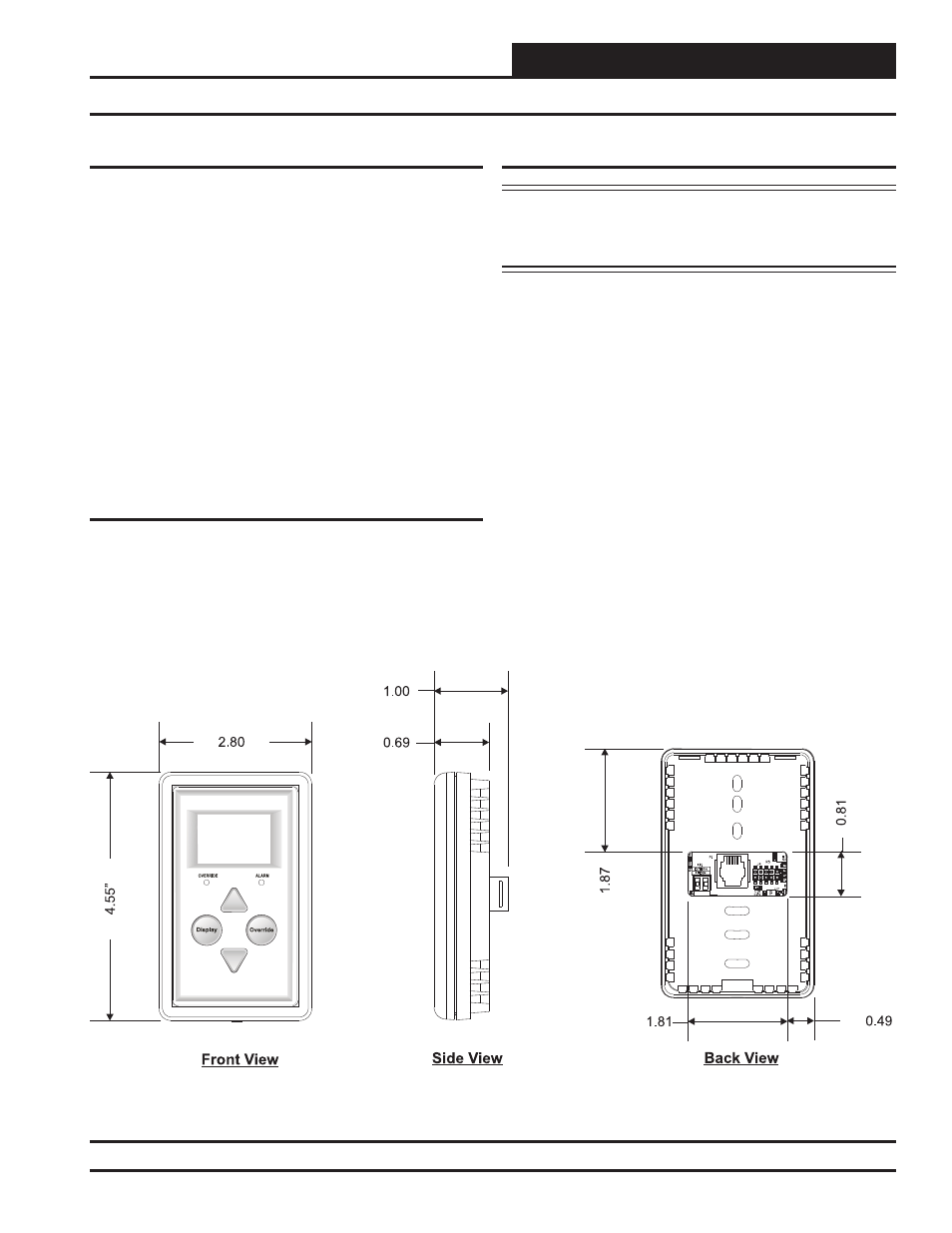
Mounting and Wiring
Figure 3: Digital Room Sensor Dimensions