Digital room sensor, Troubleshooting, Operator interface – Orion System Digital Room v.1 User Manual
Page 7
Operator Interface
DIGITAL ROOM SENSOR
7
Troubleshooting
Table 1: Temperature/Resistance for Type III 10K Ohm Thermistor Sensors
Temperature – Resistance – Voltage for
Type III 10K Ohm Thermistor Sensors
Temp
(ºF)
Resistance
(Ohms)
-10
93333
-5
80531
0
69822
5
60552
10
52500
15
45902
20
40147
25
35165
30
30805
35
27140
40
23874
45
21094
50
18655
52
17799
54
16956
56
16164
58
15385
60
14681
62
14014
64
13382
66
12758
68
12191
69
11906
70
11652
Temperature – Resistance – Voltage for
Type III 10K Ohm Thermistor Sensors
Temp
(ºF)
Resistance
(Ohms)
71
11379
72
11136
73
10878
74
10625
75
10398
76
10158
78
9711
80
9302
82
8893
84
8514
86
8153
88
7805
90
7472
95
6716
100
6047
105
5453
110
4923
115
4449
120
4030
125
3656
130
3317
135
3015
140
2743
145
2502
150
2288
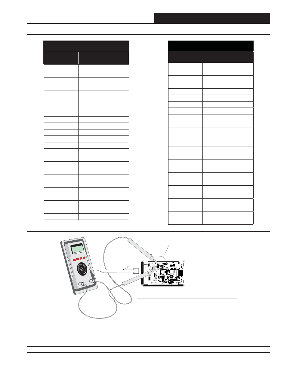
Figure 9: Temperature/Resistance Testing
+
-
T
Digital Room Sensor
Back View
9302
MICR
OC
HIP
PIC
24H
J
256G
P206
NOTE:
,
Table 1
For This Test The Sensor Must Be Disconnected From
Its TSDRSC Cable As Shown. The Meter Must Be Set To
Measure Resistance in Ohms. Use
To Determine If The
Sensor Is Reading The Correct Resistance Value For The
Ambient Temperature. This Resistance Value Should Match The
Temperature Value Listed Next To The Resistance Value In The
Table. The Temperature Should Be Measured With A Separate
Accurate Temperature Measuring Device Located In The Area
Where The Sensor Is Currently Located.
Test Points Labeled
“Extern Therm” On
Sensor Circuit Board
+
-
TSDRSC Cable
From
Sensor To The
VAV/Zone or VCM-X
Controller Modular
Sensor Port
Disconnected