Specifications (approx.) – Paloma PH-28c Indoor and Outdoor User Manual
Page 39
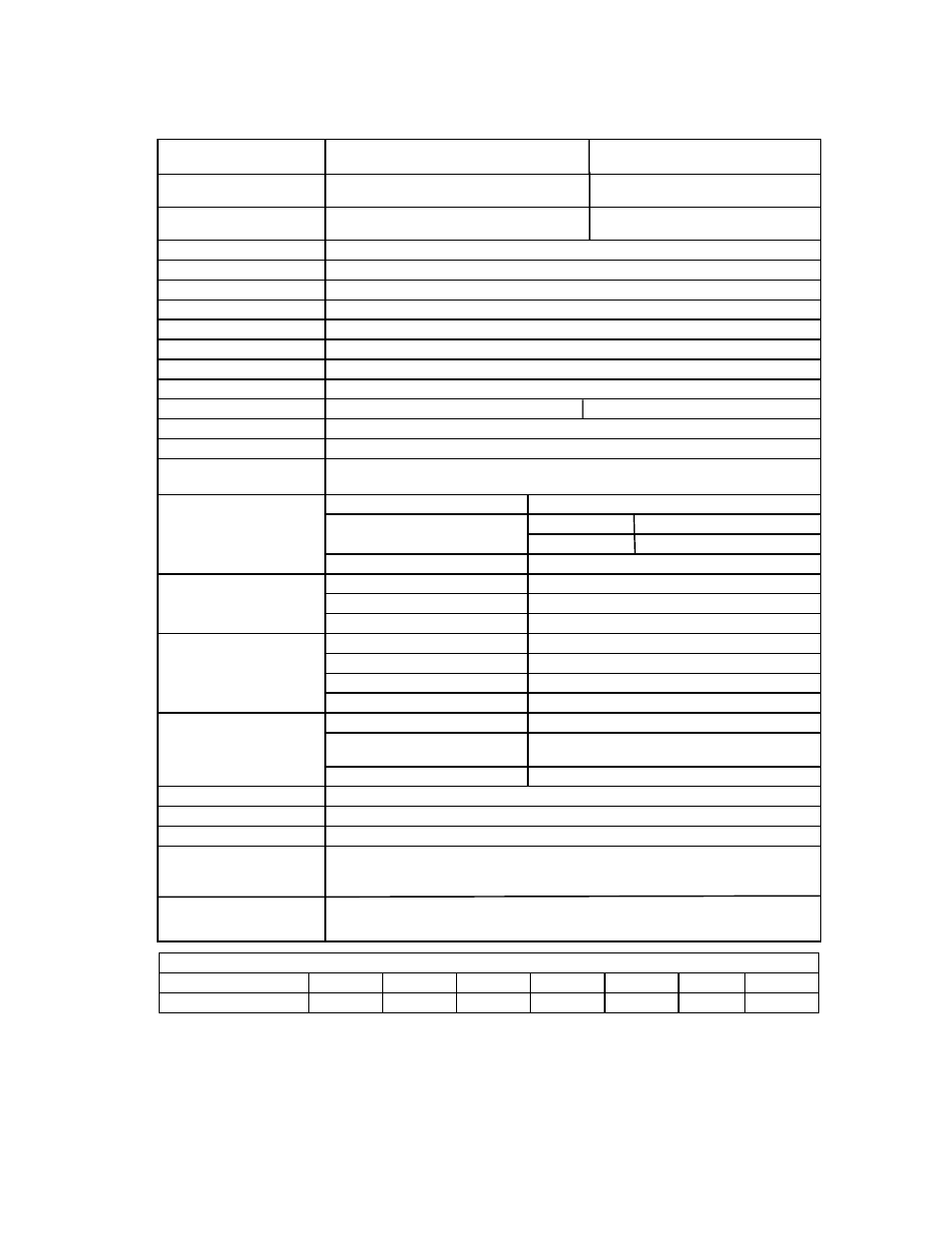
SPECIFICATIONS (Approx.)
Model
PH-28CIFSN Indoor (Natural Gas) PH-28COFN Outdoor (Natural Gas)
PH-28CIFSP Indoor (L. P. Gas) PH-28COFP Outdoor (L.P. Gas)
Rated Gas Input
(Btu/Hr.)
19,000 (Min.) 19,000 (Min.)
199,900 (Max.) (Modulating) 199,900 (Max.) (Modulating)
Installation
Indoor Wall Mounting Type Outdoor Wall Mounting Type
Vent Horizontally (Side-Wall) or Vertically
Dimensions (inches)
14 7/8 (W) x 25 3/8 (H) x 11 1/8 (D)
Net Weight (lbs)
55
Working Water Pressure
14 psi (Min.); 150 psi (Max.)
Min. Water Flow
0.66 Gallons/Minute
Max. Flow Rate
7.4 GPM at 45ºF Temperature Rise, 23 psi
Gas Connection
3/4” NPT Female (With Supplied Gas Shutoff Valve)
Water Connection
3/4” NPT Male
Manifold Pressure (in. w.c.) Contact your distributor, dealer whom you purchased or Paloma
Vent Size
4” Special Venting N/A (Outdoor Installation)
Efficiency Rating
84%
Energy Factor
0.82
Inlet Gas Pressure
before water heater
Natural Gas: Min.: 4.0”w.c.; Max.: 10.5”w.c. (Do not exceed
L.P. Gas: Min.: 8.0”w.c.; Max.: 14.0”w.c. maximum pressure.)
Hot Water Supply
Factory Setting
100ºF ~ 120ºF
Adjusting Range
Main Control 100ºF ~ 180ºF
Bath Control 100ºF ~ 120ºF
Max. Setting
Up to 180ºF (With Main Control & Dip Switch)
Combustion
System
Fan Assisted Combustion
Main Burner
Bunsen Type Burner
Ignition
Electric Continuous Sparking Ignition
Electric Portion
Electric Rating
120 VAC/60Hz, Less than 2 Amps
Wire
3 Pin Power Supply Cord 10 Feet (Indoor)
Fuse
3A Fuse x 2
Fan Motor
Turbo Fan
Safety Devices
Oxygen Depletion Safety Device Sensing Burner (Indoor Model Only)
Overheat Limiter for Heat
Exchanger
Film Type Overheat Limiter for Entire
Heat Exchanger
Flame Failure Safety Device
Flame Rod Type
Max. Vent Length
37 Feet 6 Inches Three 90 Degree Elbows
Freeze Protection
Minus 30ºF (Without Wind-Chill Factor)
Remote Control
One Digital Main Remote Control (UMC-117) is included.
Manifold Installation
Optional Controls
Manifold Installation 2 Units ~ 6 Units (With Optional MIC-180 Control)
Manifold Installation 7 Units ~ 20 Units (With Optional MICS-180 Control)
Optional Communication Cables (16, 32 & 65 feet)
Digital First Bath Remote Control (USC1-117)
Digital Second Bath Remote Control (USC2-117)
Hot Water Flow Rate and Temperature Rise
Temperature Rise (ºF)
45
50
60
70
80
90
100
Water Flow Rate (GPM)
7.4
6.7
5.6
4.8
4.2
3.7
3.4
Special Venting (Adapter, vent pipe, elbow, vent terminal, etc.) should be UL 1738 Certified Category III
Stainless Steel Venting Material (e.g. AL29-4C) in order to avoid damage from possible condensation.
“B” vent is not permitted.
Since we are constantly improving our products, all specifications are subject to change without notice.
39