Water supply connections, continued – Paloma PH-28R IFSN User Manual
Page 17
Water Supply Connections, continued
Notice: If the water flow resistance of a
shower head is too high, the burner in the
water heater will fail to ignite. Keep the
shower head clean from debris that could
cause additional pressure drop.
Notice: If using mixing valves on the
outlet, choose one that prevents cold
water pressure from overcoming hot water
line pressure.
Notice: If multiple water heaters are
installed in a manifold system, the
water piping must be in “Parallel”. A
water pressure of 40 psi (276 kPa) is
recommended for each water heater for
proper operation of the water heaters.
Alternate Water Piping Arrangement
with Optional Valve Kit
Valve kits may be purchased and installed as
optional items. Contact your distributor or
place of purchase for details.They allow for
one person full diagnostic testing and ease
of flushing the system. The kit includes two
full port isolation valves, one for the cold
side and one for the hot side. Refer to
page 23.
Install a shutoff valve near the inlet of the
water heater for service and draining
purposes.
It is not recommended to use pipes with
smaller diameters than the water supply
connection of the water heater.
Before connecting the water supply pipe
to the water heater, open the shutoff valve
and clean out sand, debris, air, caulking
material, etc. inside the pipe. Connect to
the water inlet, then check water flow.
Close the shutoff valve and clean the
water filter.
Be sure to connect the water inlet and the
hot water outlet as shown on the water
heater. If reversed, the water heater will
not function.
Installation of unions or flexible copper
connections are recommended on the
HOT and COLD water lines, so that the
water heater may disconnect easily for
servicing, if necessary.
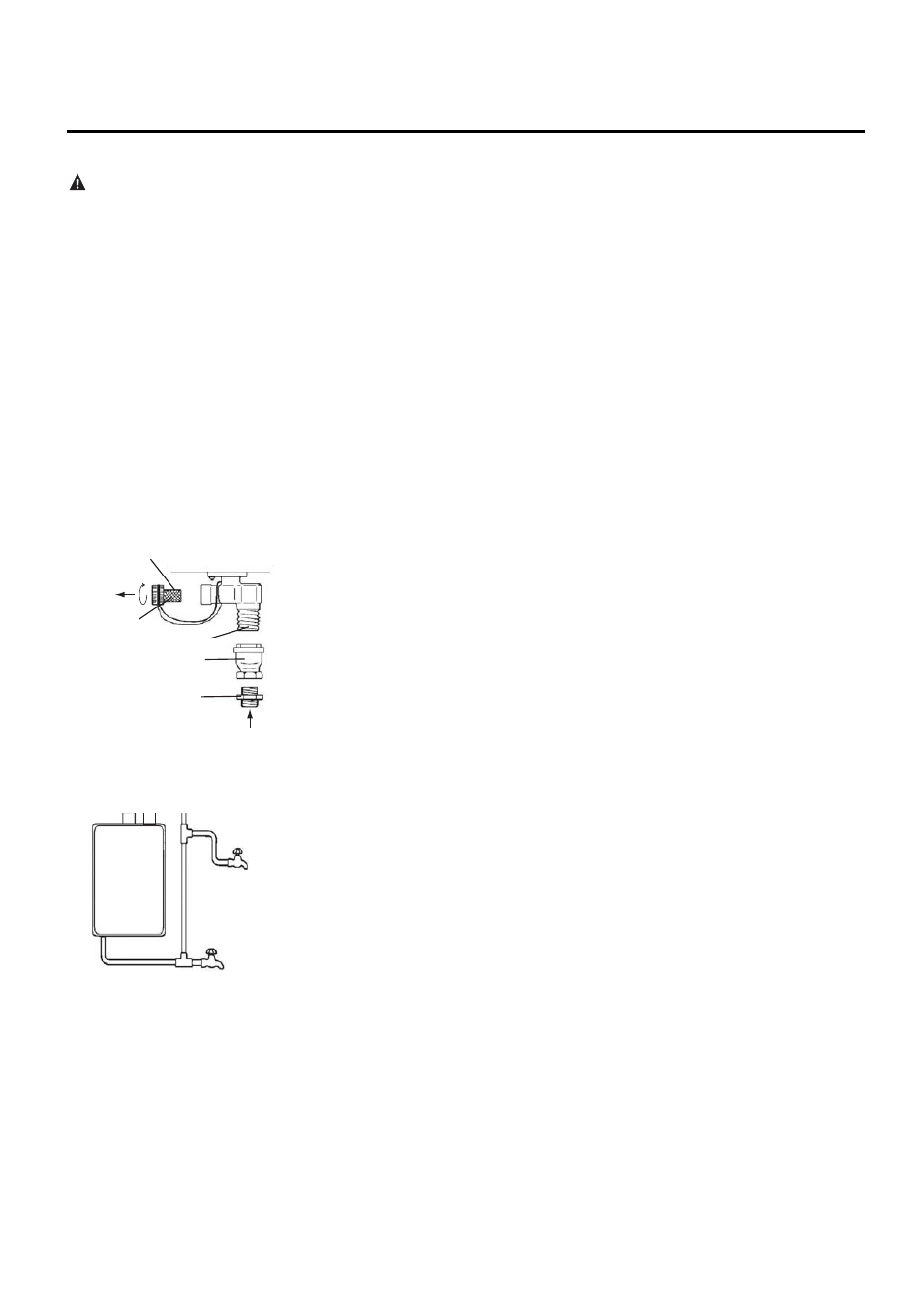
Install a Check Valve between the water
heater and the water shutoff valve (see the
top left diagram).
The following should be addressed in
regards to the HOT WATER OUTLET:
l
Connections between the water heater
and point(s) of use should be as short
and direct as possible.
l
Local codes shall govern the exact type
of pipe material that is to be used for
water connections.
l
To conserve energy and minimize heat
loss, insulation of hot water piping is
recommended (see Hot and Cold Pipe
Insulation Installation on page 24).
Notice: The flow rate of hot water may
vary when more than two faucets
(appliances, fixtures, etc.) are being used
simultaneously.
Notice: The pipes MUST be completely
drainable. If the hot water faucets are
located at a point higher than the water
heater, place a drain valve at the lowest
point (see diagram at the left).
Water Filter
Check Valve
Water Inlet
Clean the
Water Filter
Water
Nipple
Air
Relief
Valve
Hot
Water
Tap
Drain Valve
CAUTION: This water heater
must only be used with the
following water supply system
conditions:
l
With clean, potable water free
of corrosive chemicals, sand,
dirt or other contaminates.
l
With inlet water temperatures
above 32°F (0°C), but not
exceeding 120°F (49°C) for
Residential models and up to
140°F (60°C) for Commercial
models.
l
Free of lime and scale deposits.
l
DO NOT reverse the hot
and cold water connections.
The water heater will not
operate.
Notice: Use only teflon tape on cold
and hot water connections and
lines.
17
This appliance is not
intended for space heating
application. Do not
connect this heater to
waterlines previously
used for space heating
or non-potable water
distribution. All water
piping and components
shall be suitable for
potable water.