Receiver controls and functions – Relacart Electronics UR-222S User Manual
Page 5
1
2
3
4
5
6
1
2
3
4
5
6
7
8
9
10
11
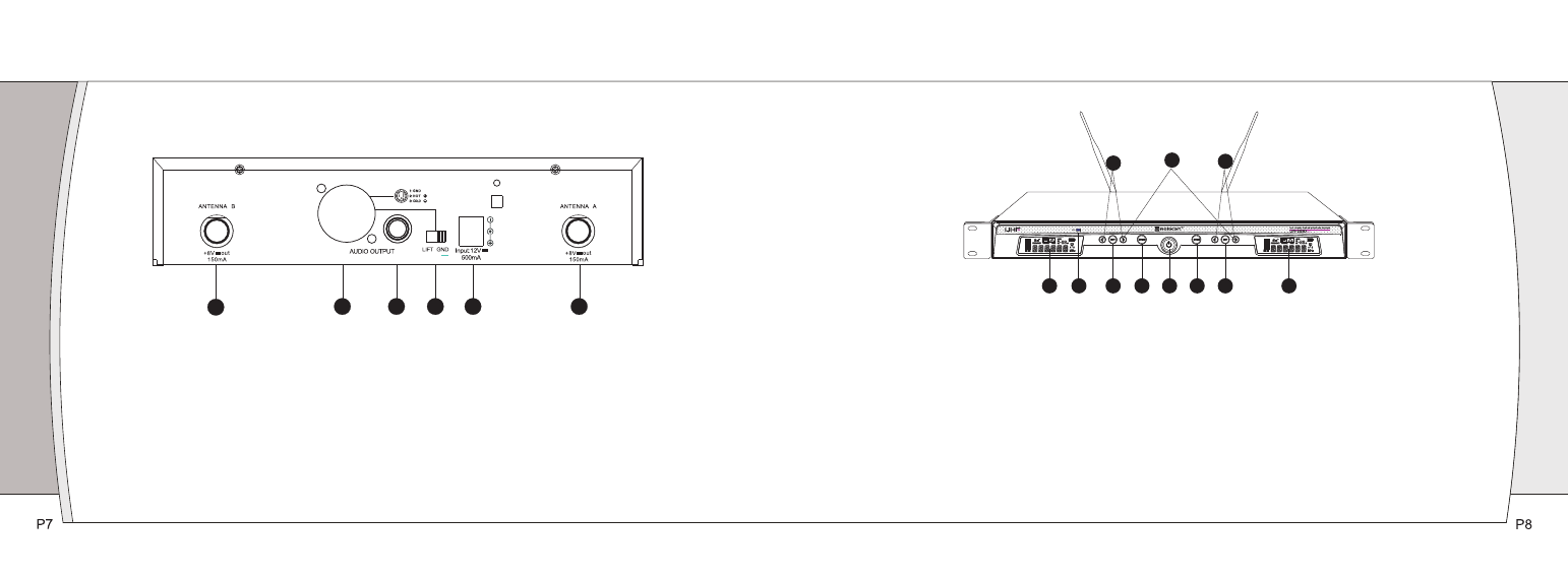
UR-222S Receiver Rear Panel
1.Antenna Input Jack: BNC type antenna connector for tuner ”B”, attached the antenna directly.
2.Balanced Output Jack: XLR type connector. A standard 2 conductor shielded cable can be used to connect
the receiver output to a balanced microphone level input on a mixer or integrated amplifier.
3.Unbalanced Mixed Output Jack: Unbalanced Mixed Output Jack: 1/4” ( 6.3mm) phone jack. Can be
connected to an aux- level input of a mixer, guitar amp or tape recorder.
4.Ground connection switch: LIFT means disconnecting with ground, GND means connecting with ground.
5.DC Power Output Jack: 12V / 700mA.
6.Antenna Input Jack: BNC type antenna connector for tuner ”A”, attached the antenna directly.
1.Power Switch:Press power switch for 3 seconds and the receiver readouts will light.
2.Infrared Data Transfer Button (SYNC): Press this button to transmit the channel data from receiver to
transmitter.
3.Infrared Data Transfer Window (iR): Transmit channel data from the receiver to the transmitter, so that
they are in the same frequency.
4.LCD screen shows working channel or frequency, RF/AF, diversity strengths; transmitter battery level,
mute and operation menu.
5.UP / DOWN Buttons:
A, Press Up or Down arrow button, in conjunction with the Set button, to step through menus, select operating
frequency and edit receiver function choices.
B, Press Up or Down arrow button 3 seconds and the receiver will auto- scan and lock on to an open,
interference-free frequency.
6.SET Button: Use in conjunction with the Up / Down arrow buttons to step through menus, choose operating
frequency and select receiver function options.
UR-222D Receiver Front Panel
Receiver Controls and functions