Sim2 HT300 E-Link User Manual
Page 22
22
����������
up the projected image.
These parameters do not normally require adjustment because
the system checks the input signal and automatically sets the
most suitable values.
However, if the image appears disturbed (loss of position within
the equidistant vertical bands or instability and lack of shar-
pness on the narrow vertical lines) it may help to prompt the
system to repeat the input signal analysis and determination
of the best parameters by calling the automatic adjustment
procedure with the AUTO key on the remote control or on the
keypad.
If the automatic procedure fails to have the required effect, enter
the frequency and phase values manually and approach the
screen sufficiently to observe the effects of the adjustments.
Y / C DELAY
In the case of Video and S-Video signals, it may be necessary
to correct horizontal colour misalignment within the projected
image. For a given video standard (e.g. PAL or NTSC) the stored
value does not normally require further fine-tuning, unless the
source or connection cable has changed.
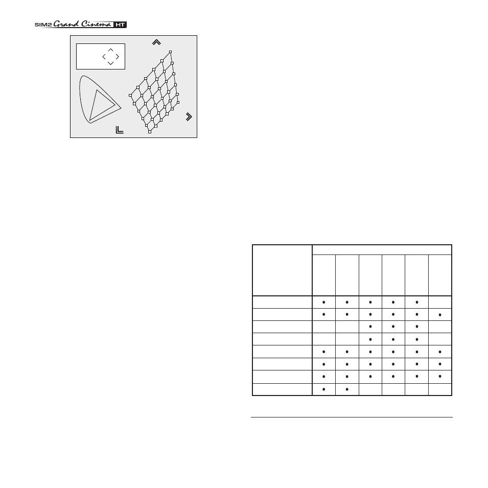
Table 5
Position
Aspect
Vi
de
o
S-V
ideo
RGBS
YCrCb
RGB Grafico
RGBS 15kHz YCrCb 15kHz
Adjustments
Inputs
Frequency
-
-
Phase
Gamma Correction
Colour Temperature
Y/C Delay
-
-
-
-
-
-
-
-
Overscan
-
DVI-D
HDMI™
SETUP
The setup menu contains less frequently used adjustments that
may be required during installation (e.g. On Screen Display
language selection or the display of Test Patterns).
��
Fig. 22
GAMMA CORRECTION
Determines the system’s response to the grey scale, emphasi-
sing or attenuating the different grades of brightness (blacks,
dark, medium, light grey, whites) in the projected image.
There are availabel up to 12 degamma curves, using these
curves it is possible choose the best curve for the signal and
the image in use.
OVERSCAN
Remove noise around image. Some sources can produce a
picture with noise along edges, thanks to the overscan function
it is possible to drop such imperfections outside the projected
area. The overscan value can be included between 0 (no
overscan) and 32 (maximum value). The image maintains in
any case the aspect.
POSITION
Use this adjustment to position the image vertically and ho-
rizontally. Determines the aspect ratio of the projected image.
These parameters do not normally require adjustment because
the system checks the input signal and automatically sets the
most suitable values.
However, if the image is not perfectly centralised it may prove
useful to request the system to repeat the input signal analysis
and image positioning, calling the automatic control procedure
from the AUTO button on the remote control or keypad. When
this procedure is called it is helpful to have a white or light co-
loured background on the screen in the current picture.
FREQUENCY/PHASE
These adjustments, available for progressive signals and for
signals from PC, ensure correspondence between the number
of pixels making up the signal and the number of pixels making