Chapter 6: communication protocol, Page 18 – Smart Avi AVRouter User Manual
Page 18
AVRouter Manual Version 1.0
Page 18
Chapter 6: Communication Protocol
Chapter 6: Communication Protocol
Chapter 6: Communication Protocol
Chapter 6: Communication Protocol
Chapter 6: Communication Protocol
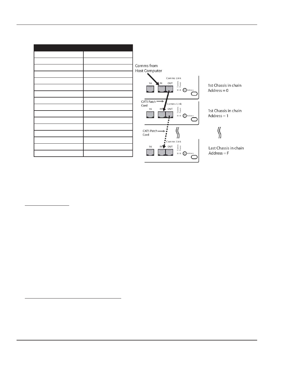
In order to ensure good communications it is essential that the Hex address switch on the front of the SmartNet-X is set
correctly. The hex switch can be adjusted using a small flat blade screwdriver.
An incorrect setting or having more than one chassis set to the same address will result in comms errors.
6.0 Packet Structure
6.0 Packet Structure
6.0 Packet Structure
6.0 Packet Structure
6.0 Packet Structure
The general form of packets sent to the SmartNet-X switches are detailed below;
<Header Byte 0><Header Byte 1><Frame Address><Reserved><CMD><DATA BYTES><BCC>
<Header Byte 0><Header Byte 1><Frame Address><Reserved><CMD><DATA BYTES><BCC>
<Header Byte 0><Header Byte 1><Frame Address><Reserved><CMD><DATA BYTES><BCC>
<Header Byte 0><Header Byte 1><Frame Address><Reserved><CMD><DATA BYTES><BCC>
<Header Byte 0><Header Byte 1><Frame Address><Reserved><CMD><DATA BYTES><BCC>
Where ;
<Header Byte 0>
<Header Byte 0>
<Header Byte 0>
<Header Byte 0>
<Header Byte 0>
Always 0xBE
<Header Byte 1>
<Header Byte 1>
<Header Byte 1>
<Header Byte 1>
<Header Byte 1>
Always 0xEF
<Address>
<Address>
<Address>
<Address>
<Address>
Frame address. Set by Hex switch on front of unit.
<Reserved>
<Reserved>
<Reserved>
<Reserved>
<Reserved>
Reserved for future use (Always 0x00)
<CMD>
<CMD>
<CMD>
<CMD>
<CMD>
Command byte – Determines the number of bytes in DATA BYTES
<DATA BYTES>
<DATA BYTES>
<DATA BYTES>
<DATA BYTES>
<DATA BYTES>
Number of bytes for associated CMD
< B C C >
< B C C >
< B C C >
< B C C >
< B C C >
XOR of all bytes in the string up to but not including BCC
On receipt of a valid data packet the SmartNet-X will either respond with an ACK (0x06) or a valid packet
containing the requested data.
7.0 Implemented Commands @ 18/11/2003
7.0 Implemented Commands @ 18/11/2003
7.0 Implemented Commands @ 18/11/2003
7.0 Implemented Commands @ 18/11/2003
7.0 Implemented Commands @ 18/11/2003
Note:
Note:
Note:
Note:
Note: Commas shown in example byte strings below are not transmitted from the serial port they have only been
added only to aid legibility.
7.1 Set Crosspoint Command : CMD = 0x00
7.1 Set Crosspoint Command : CMD = 0x00
7.1 Set Crosspoint Command : CMD = 0x00
7.1 Set Crosspoint Command : CMD = 0x00
7.1 Set Crosspoint Command : CMD = 0x00
Sets specified switch output or Destination to the specified input or Source.
Send: <0xBE><0xEF><Address><0x00><0x00><Source><Destination><BCC>
Send: <0xBE><0xEF><Address><0x00><0x00><Source><Destination><BCC>
Send: <0xBE><0xEF><Address><0x00><0x00><Source><Destination><BCC>
Send: <0xBE><0xEF><Address><0x00><0x00><Source><Destination><BCC>
Send: <0xBE><0xEF><Address><0x00><0x00><Source><Destination><BCC>
This is achieved by creating a loop between chassis using the comms IN and OUT ports on the front of the chassis.
i.e.
s
s
e
r
d
d
A
s
s
e
r
d
d
A
s
s
e
r
d
d
A
s
s
e
r
d
d
A
s
s
e
r
d
d
A
g
n
i
t
t
e
S
h
c
t
i
w
S
x
e
H
g
n
i
t
t
e
S
h
c
t
i
w
S
x
e
H
g
n
i
t
t
e
S
h
c
t
i
w
S
x
e
H
g
n
i
t
t
e
S
h
c
t
i
w
S
x
e
H
g
n
i
t
t
e
S
h
c
t
i
w
S
x
e
H
00000
00000
11111
11111
22222
22222
33333
33333
44444
44444
55555
55555
66666
66666
77777
77777
88888
88888
99999
99999
0
10
10
10
10
1
A
A
A
A
A
1
11
11
11
11
1
B
BBBB
2
12
12
12
12
1
C
C
C
C
C
3
13
13
13
13
1
D
D
D
D
D
4
14
14
14
14
1
EEEEE
5
15
15
15
15
1
FFFFF