Calibration procedure for mkp - pkp, 3 calibration procedure – Super Systems 20PQ Calibration Manual User Manual
Page 3
3
Calibration procedure for MKP - PKP
2.4 IN CT / FEEDBACK SELECTION
This instrument can use the "IN CT" input or the "Feedback" input;
the two inputs are not contemporarily.
The current transformer input allows you to measure and display the
current running in a load driven by a time proportional control output
during the ON and OFF periods of the output cycle time. By this
feature it is also available the "Out failure detection" function (see
page 66 in the USER MANUAL).
The feedback input is used when the servomotor close loop or the
servomotor open loop with valve position indication outputs is
required.
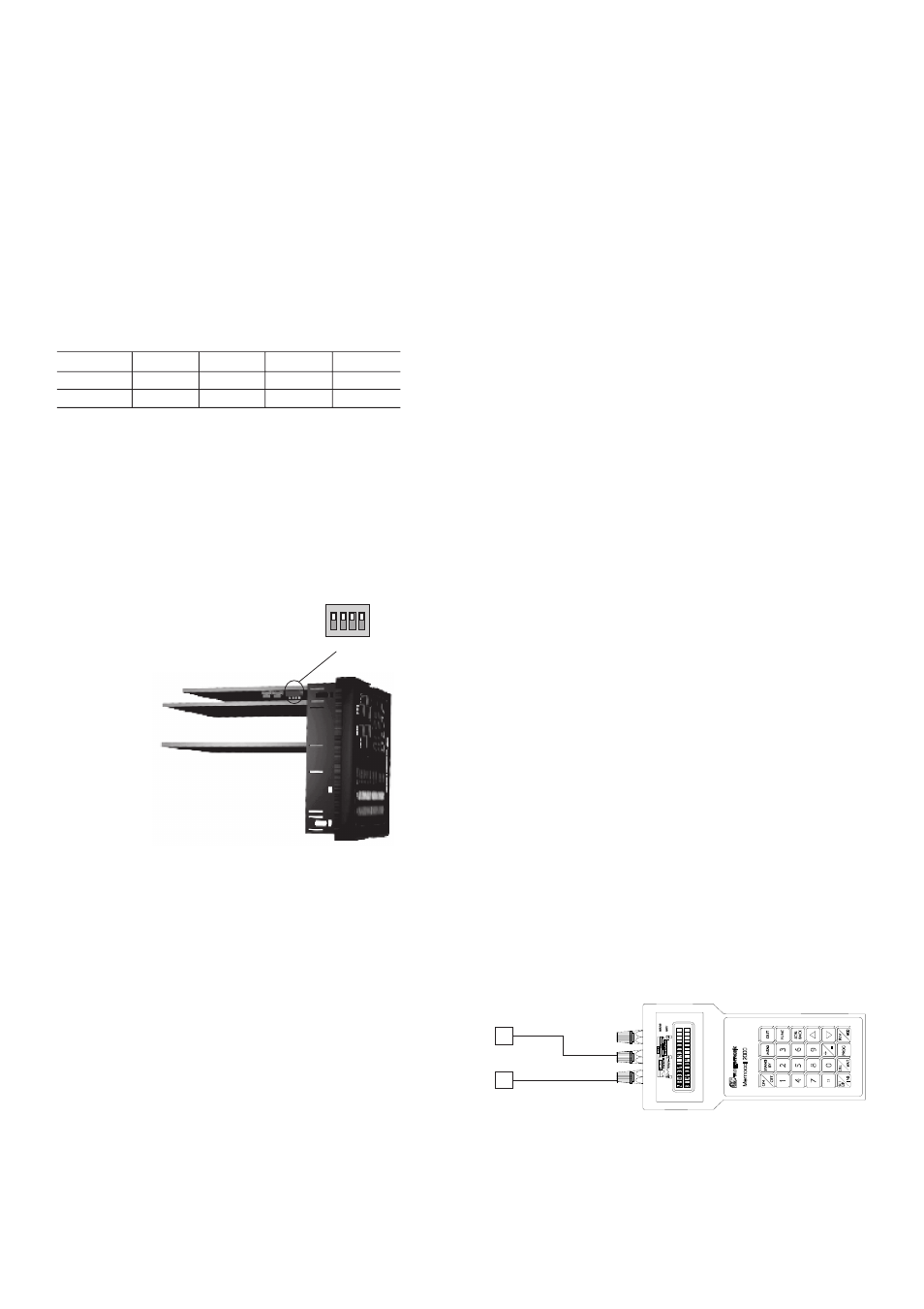
To select the desired input type, set V301 (see fig. 3) as detailed in
the following table:
Input
V301.1
V301.2
V301.3
V301.4
IN CT
ON
OFF
ON
ON
Feedback
OFF
ON
OFF
ON
2.5 CALIBRATION MODE SELECTION
To start the calibration procedure, the DIP SWITCH V101, mounted
on CPU card, must be set as follows:
V101.1 = Not care condition
V101.2 = OFF
V101.3 = Not care condition
V101.4 = ON
NOTE: during calibration procedure the serial communication
interface will be disabled.
Fig. 4
When it is desired to exit from calibration mode proceed as follows:
1) switch off the instrument;
2) remove the instrument from its case;
3) select the desired operative mode by setting the DIP switch V101
as described in "Operative mode and hardware lock" paragraph
reported at page 23 of the USER MANUAL.
3 CALIBRATION PROCEDURE
3.1 FOREWORD
Calibration parameters are divided in groups.
Each group is comprised of two parameters (initial and full scale
values) plus a specific calibration check.
Follows a complete list of the "calibrations groups".
1)
ñ.I.tc
= Main input calibration, TC input
2)
ñ.I.CJ
= Main input calibration, cold junction
3)
ñ.I.rt
= Main input calibration, RTD input
4)
ñ.I.ñA
= Main input calibration, mA input
5)
ñ.I.5
= Main input calibration, 5 V input
6)
ñ.I.10
= Main input calibration, 10 V input
7)
A.I.ñA = Auxiliary input calibration, mA input
8)
A.I.5
= Auxiliary input calibration, 5 V input
9)
A.I.10
= Auxiliary input calibration, 10 V input
10)
In.Ct
= Current transformer input calibration
11)
FEEd
= Feedback input
12)
05.ñA
= Out 5 calibration
13)
06.ñA
= Out 6 calibration
14)
CAL
= Default calibration data loading
NOTE: Calibration groups from group 7 to group 13 will be shown
only when the specific hardware is fitted.
GENERAL NOTE ABOUT CALIBRATION PROCEDURE:
During calibration procedure, when the initial or full scale value of a
group is selected and the middle display shows "OFF", pushing the
FUNC pushbutton the instrument will jump to the next parameter or
check without to modify the previous calibration setting.
In this way it is possible to recalibrate only the desired input or output.
It is also possibe to make a check of one or more calibration group
without to remake the specific calibration.
3.2 CALIBRATION PROCEDURE
HOW TO PROCEED
Switch on the instrument, the upper display will show CAL while the
lower display will show the firmware version.
Push the FUNC pushbutton to display the first calibration group on
the upper display. Depress FUNC pushbutton more times until the
desired calibration group is reached.
1) "ñ.I.tc" - MAIN INPUT CALIBRATION - TC INPUT
The upper display will show "ñ.I.tc".
1.1) "Lr" - INITIAL SCALE VALUE
The lower display will show "Lr"
a) Made the specific hardware setting as described at paragraph 2.
b) Connect the instrument under test to the calibrator as shown in
Fig. 5.
Fig.5
c) The upper display will show "ñ.I.tc", the lower display will show
"Lr" while "OFF" will appear on the middle display.
d) Set calibrator to 0.000 mV.
e) Push
▲
pushbutton, the middle display will change to "On".
f) After few seconds, start calibration by pushing FUNC
pushbutton. At the end of this calibration routine, the instrument
will go to the next step.
1 2 3 4
ON DIP
V101
1
_
+
3