SVS PLASMA ONE 4 User Manual
Page 13
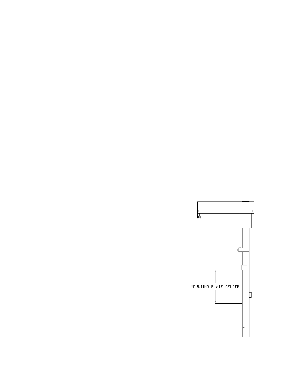
a. Positioning the Boom Mounting Plate
•
The plate is attached to the boom by three (3)
3
/
8
-inch-16 flathead Allen bolts and Unistrut nuts. The
rectangle nuts are set into the slot of the boom with their locking grooves set into the edges of the slot.
Anytime that the nuts are loosened they must be checked to see that they are properly positioned with
their locking grooves set into the edges of the slot.
•
To calculate the position of the boom mounting plate center divide the height of the screen in half and
add 3-inches [7.6 cm]. Measure down from the Up Limit Switch Reinforcement Plate on the boom and
place the center of the screen mounting plate at this location. Tighten all three (3)
3
/
8
-inch-16 flathead
Allen bolts. See Figure 10.
b. Attaching the Screen Mount to the Boom Mounting Plate
•
Attach the screen mount (centered side-to-side and top-to-bottom) to the boom mounting plate by
drilling four (4)
3
/
8
-inch-16 holes in the boom mounting plate and screen mount. You may use existing
holes in the screen mount if they will allow the attaching the screen mount to the boom mounting plate.
•
Secure the screen mount to the boom mounting plate by tightening all mounting hardware.
c. Installing the Screen on the Screen Mount
•
Install the screen onto the screen mount using the manufacturers instructions. Ensure that the screen is
level and balanced. There should be appropriately 2-inches [5 cm] of clearance all the way around the
screen.
•
Failure to maintain proper clearance could damage the screen, lift and/or ceiling.
•
Using the Wall Plate Controller, raise the lift toward the up position, stopping frequently to check all
clearances (screen, lift, and ceiling closure). Make sure that there are no obstructions in the path of the
lift or in the ceiling cavity where the screen will be stored.
•
Screen cabling can be attached either to the boom or ceiling
closure.
11. Lift Tilt Adjustment
•
The boom tilt is factory set to zero degrees. The screen will need
to be installed first on the screen to determine the exact amount of
tilt required. The tilt is adjusted by loosening the top
3
/
8
-inch-16
bolt screwed on the microswitch bracket. The microswitch bracket
is connected to a limit switch, when in contact with the boom
stops the lift. There must be positive weight forward of the boom
to achieve tilt. See Figure 11.
a. To Adjust Tilt:
•
Lower the lift.
•
Set the key switch to the OFF position.
•
Loosen the
3
/
8
-inch-16 bolt and Unistrut nut on the down limit
microswitch bracket. See Figure 11.
•
Slide the down limit microswitch bracket forward to increase the
boom tilt and backwards to decrease the tilt. The stop bolt will
contact the boom.
SVS Plasma One 4 Lift Installation Instructions
Page 13 of 16