Expansion connector wiring diagram – TE Technology TC-24-25 User Manual
Page 14
14
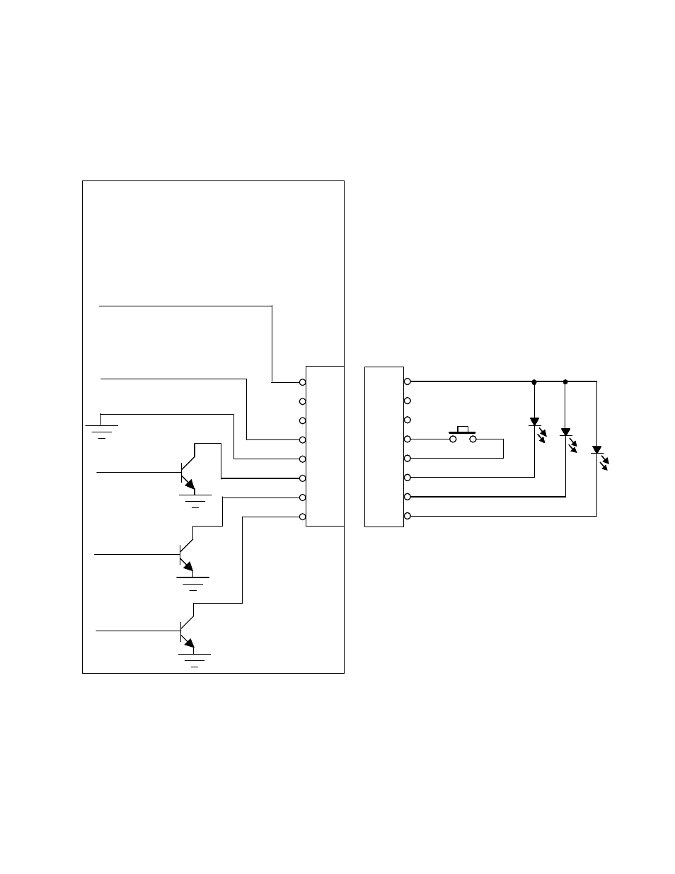
Expansion Connector Wiring Diagram
Note: The 25 mA current source is a true current source. Maximum compliance voltage is approximately
equal to the input voltage to the temperature controller. No external current limit resistors are needed for
the LED. The LED must be capable of being driven with a 25 mA continuous current.
8
7
6
5
4
3
2
1
Expansion Connector
Molex 22-23-2081
25 mA Current Source
Alarm Cancel
Input Common
High Alarm
Low Alarm
No Alarm
JP2
8
7
6
5
4
3
2
1
Customer- supplied
Connector
Note: Pins 6 and 7 not functionally defined.
Please do not connect.
8
7
6
5
4
3
2
1
Expansion Connector
Molex 22-23-2081
25 mA Current Source
Alarm Cancel
Input Common
High Alarm
Low Alarm
No Alarm
JP2
8
7
6
5
4
3
2
1
Customer- supplied
Connector
Note: Pins 6 and 7 not functionally defined.
Please do not connect.