Tecfluid SC-250 User Manual
Page 5
5
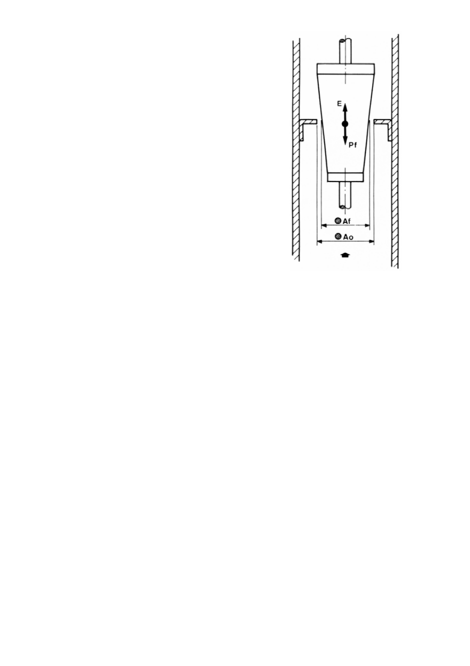
Working principle
The flow meter consists of a calibrated orifice and a
conical float. The rising flow pushes the float to an
equilibrium point. The area obtained between the float
and the orifice is proportional to the flow rate.
This type of measuring principle is known as variable
area.
The equilibrium point depends on :
−
The float weight :
Pf
−
The fluid thrust :
E
−
The free flow area :
Al
The area proportional to the flow rate will be:
Al = Ao - Af
where:
Ao = Area of calibrated orifice
Af = Float area
RECEPTION
The SC-250 series flow meters are supplied tested in our calibration rigs, ready for installation and
service.
The instruments are supplied packed for their protection during transport and storage. Likewise
they have blocking elements that should be removed before installation.
With the instrument in a vertical position, check that the float moves freely and that the indicating
needle, starting from zero, follows the float movements over the whole scale and returns to zero.
The float displacement should be done manually without jerks, with the flow meter in a VERTICAL
position and the zero of the scale at the bottom.
FLOW METER INSTALLATION. (Figures 1, 2, 3 & 4)
The flow meter must be installed in a vertical position with rising flow direction.
It is important that the position is completely vertical, given that deviations of about 5º can produce
errors of about 8-10% of the reading due to friction on the float.
In the case of an installation with horizontal flow direction, the flow meter should be installed as
shown in figure 1.
In the case of an installation with vertical falling flow direction, the flow meter should be installed as
shown in figure 2.